Continue to Site

Welcome to EDAboard.com

Welcome to our site! EDAboard.com is an international Electronics Discussion Forum focused on EDA software, circuits, schematics, books, theory, papers, asic, pld, 8051, DSP, Network, RF, Analog Design, PCB, Service Manuals... and a whole lot more! To participate you need to register. Registration is free. Click here to register now.

Help me fix mistakes in an ultrasonic range meter

Status
Not open for further replies.

mlodyfn

Newbie level 3
Joined
Aug 28, 2012
Messages
3
Helped
0
Reputation
0
Reaction score
0
Trophy points
1,281
Location
Germany
Activity points
1,313
Hi,
I have made an ultrasonic range meter but it doesn't work as I wish.
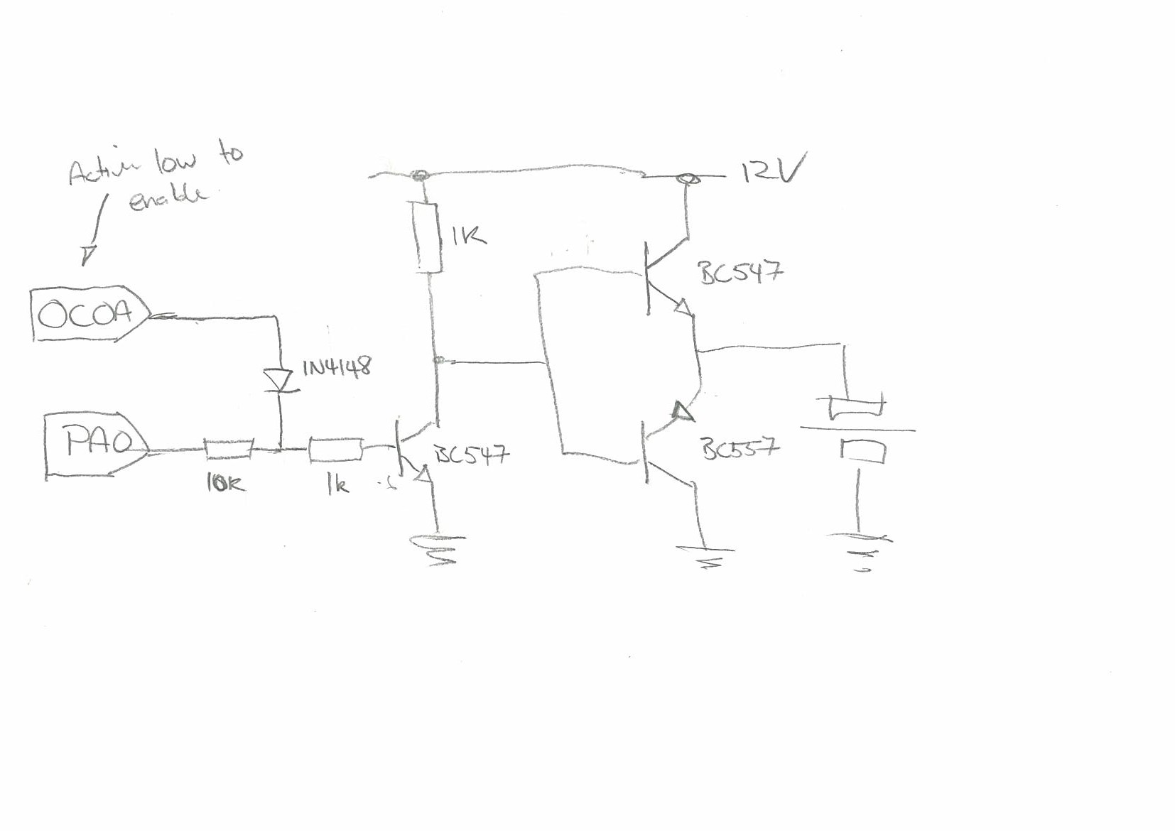
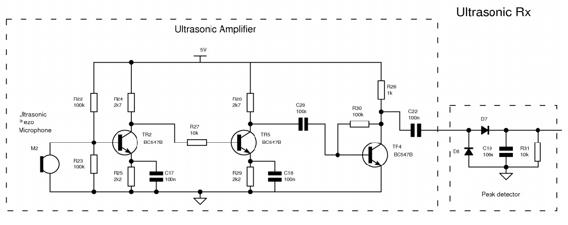
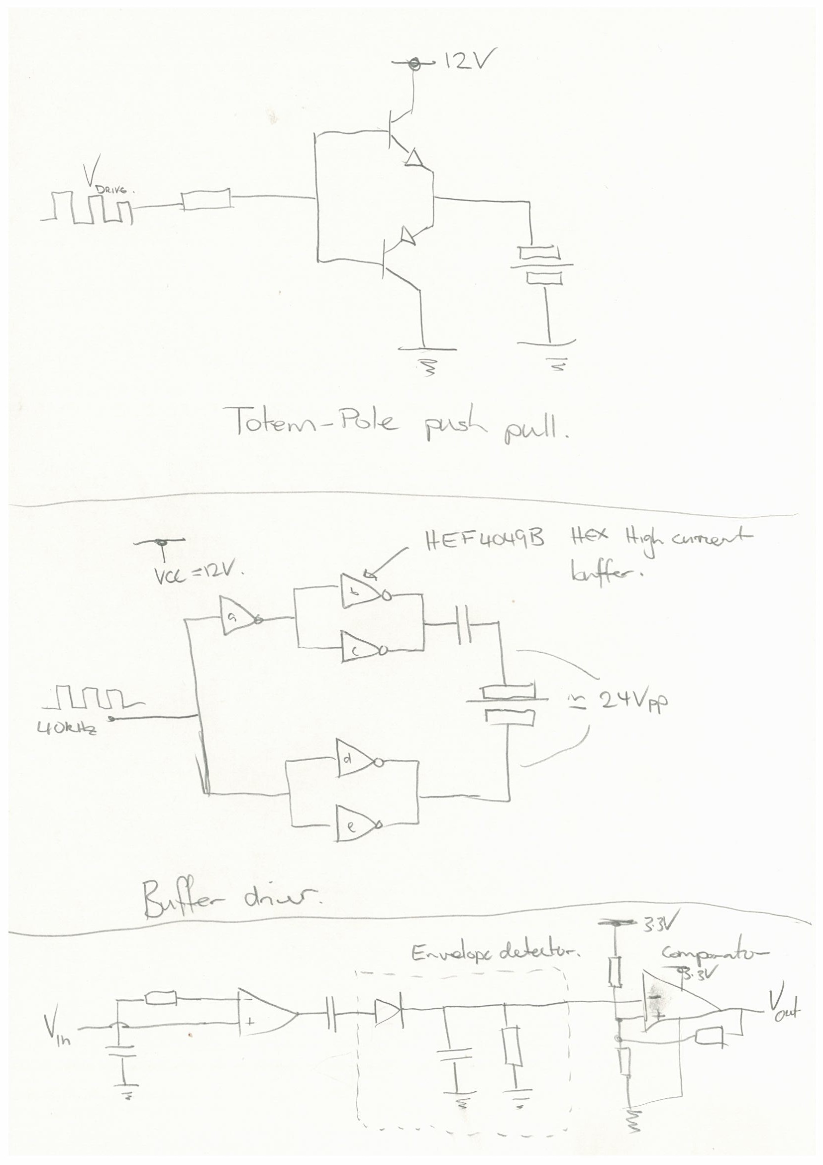
I use timer0 in CTC mode to generate 40 kHz signal, and 3 transitors for signal 40 kHz with amplitude 12 V - Transmitter part on schematic,I use non symetric power supply for amplifier so I use voltage divider for -/+ 6 V Power supply amplifier +/- 6V part on schematic. Amplifier - Microcontroller part turns voltage from amplifier to 3,6 V on ICP of microcontroller.

Problems about circuit:

-After connecting the ultrasonic sensor voltage on JP2 ( collector Q4) falls to mV but without it voltage is about 12 V.
- With connected receiver but without connected transmitter TL082 is always amplifing some signal 50 Hz


Can someone tell me where are mistakes on schematic. I'm sorry for my English ;(
 

Attachments

  • ultrasonic.pdf
    37.9 KB · Views: 116

Re: Ultrasonic range meter

Is your transducer capacitive? What is the voltage on the base of Q4? I don't quire understand you receiver schematic. YOU have a noninverting label but I don't see where it comes from and also why is C4 in series with R5. 50Hz signal seems that you may be having some feedthrough from the AC supply somewhere. You need to separate the power supply from the receiving circuit and give the receiving circuit it own supply bypass capacitor close to it. Shield its input lines and make them as short as possible. Make sure your transducer lines are shielded and the shield is connected to ground. That would reduce the stray pickup of 50Hz.
 

Re: Ultrasonic range meter

What's connected to JP2? A piezo transducer is high impedance and won't short the driver circuit.

The base circuit of T1 doesn't look like working well for 40 kHz, a BE-resistor should be added.

P.S.:
I don't quire understand you receiver schematic.
The schematic is dreadful confusing, but the amplifier should work. The receiving transducer is connected to JP4. 6V Virtual ground seems to be filtered somehow, If not from an unshielded cable, 50 Hz interferences are probably picked up by the amplifier circuit itself. Or the 12V supply is unregulated.
 
Last edited:

Re: Ultrasonic range meter

P.S.:
The schematic is dreadful confusing, but the amplifier should work. The receiving transducer is connected to JP4. 6V Virtual ground seems to be filtered somehow, If not from an unshielded cable, 50 Hz interferences are probably picked up by the amplifier circuit itself. Or the 12V supply is unregulated.

I see. It would help to decrease your capacitance C4 to maybe 100n to help the amplifier reject low frequencies.
 
  • Like
Reactions: FvM

    FvM

    Points: 2
    Helpful Answer Positive Rating
Re: Ultrasonic range meter

G'day,

Transmitter:
Your transmitter stage won't work, (very well.. if at all!) I'm going to take a stab in the dark and assume you're using a piezo transducer?... as the voltage is too low for an electrostatic device and a moving coil loudspeaker will probably require a lot more puff than a 557 can huff. (however... if you are using a moving coil loudspeaker.. this could perhaps explain why your Collector voltage is bottoming out.. how are you measuring it - CRO DMM?)

If you are using a piezo then your driver isn't correct.. Lets assume the most basic model of a piezo, a capacitor. If you replaced the transducer with a capacitor what would happen? it would charge up when Q4 was activated and stay charged when it turns off... there's no return path to discharge the cap when Q4 goes off... In other words you're only pushing.. you need some pull... hence the push-pull output stage or totem-pole configuration. Ideally though, you would use a bridge to drive your transducer thus operating in full defection mode rather than half. The best and most reliable way I've found to pack plenty of punch with the least component count is to use a HEF4049B high current hex inverting buffer... it will run up to 18V which in theory equates to a whopping 36Vpp across your transducer. (Check all your currents are within spec though!).

Receiver:
Gotta agree with the other fellers.. tricky schematic to follow.. but.. first things first... How have you connected the power supply to the TL082? I say this because the TL08x devices aren't specified to run on a single supply... (they probably will though, but have never tried however if they do your configuration should be OK). Thy're also not rail to rail... so if you're saturating them, odd things will happen. (Odd things still happen with rail to rail devices as well, but they tend to be a little more forgiving). Have a look at the Microchip rail to rail devices they'll also allow you go direct into the micro. That said, it's a pretty crude receiver stage if you're hoping to recover the actual 40Khz waveform on the capture compare port... I would be thinking of at least using a comparator in place of IC5B and you would really need a AGC for optimal results. Might I suggest a simpler method, very reliable with the loss of some accuracy... an envelope detector... As with your 50Hz... maybe try working off a battery first... get things working then track down the noise problems?


- - - Updated - - -

In relation to R5 and C4 being in series... it's a half supply biased non-inverting amp... so C4 is a DC block to ensure the inverting input maintains the virtual reference voltage of the non-inverting input... hence the large size - basically a short to AC.
 

Re: Ultrasonic range meter

How have you connected the power supply to the TL082? I say this because the TL08x devices aren't specified to run on a single supply...
They are obviously supplied by 12V single supply, which is just O.K. for the present circuit. There are many ways to simplify it anyway.
 

Re: Ultrasonic range meter

In relation to R5 and C4 being in series... it's a half supply biased non-inverting amp... so C4 is a DC block to ensure the inverting input maintains the virtual reference voltage of the non-inverting input... hence the large size - basically a short to AC.

Having C4 provides high pass characteristics to the non inverting amplifier since it has a gain of 1 for low frequencies and the higher gain at high frequencies. Reducing C4 will provide better rejection to the 50Hz that is being seen at the output.
 
Last edited:

Re: Ultrasonic range meter

Thanks for all answers. I have changed schematic now it is less confusing I hope so. Can I make virtual ground without C18 and C4 ( old schematic) ?

The transmitter part now is like Thunderdantheman suggested because transmitter is a piezo ULTRASONIC SENSOR. I will try to built it on breadboard and check any 50 Hz interferences from amplifier or power supplier.
If it wont work i will try with envelope detector
 

Attachments

  • sonic1.pdf
    33.5 KB · Views: 89

The transmitter part now is like Thunderdantheman suggested
The point he didn't mention is that the circuit needs 12 V input square wave, not 4.3 V or whatever your transistor AND gate provides. And there should be a pull-down resistor, as previously mentioned.
 

Nicely pointed out FvM... you will need to drive the totem-pole (and the hex buffer for that matter) with your 40kHz square wave pumped up to 12V..... have a play with this circuit... i haven't tested it but looks like it will work ;)


Yep... you're old op-amp configuration looked OK... aryajur is correct.. lower the cap a bit it might help with the 50Hz. HOWEVER.... Your op-amp configuration is totally up the creek in this latest design.... you have positive feedback... compare it to you old design!

Good luck! let me know how it goes!
 
  • Like
Reactions: FvM

    FvM

    Points: 2
    Helpful Answer Positive Rating
By the way, I wonder why the circuit implements a hardware gate for the 40 kHz signal. Reconfiguring the pin clock output on the fly should achieve the same without needing two pins and external hardware.
 

By the way, I wonder why the circuit implements a hardware gate for the 40 kHz signal. Reconfiguring the pin clock output on the fly should achieve the same without needing two pins and external hardware.

I really dont know why I did not do it by software. I have built the totem-pole and it works nice. But amplifier doesn't work well i reach the 1 inch range with larger gain circuit amplify some noise . Can I built something like that ?
 

Status
Not open for further replies.

Part and Inventory Search

Welcome to EDABoard.com

Sponsor

Back
Top