Continue to Site

Welcome to EDAboard.com

Welcome to our site! EDAboard.com is an international Electronics Discussion Forum focused on EDA software, circuits, schematics, books, theory, papers, asic, pld, 8051, DSP, Network, RF, Analog Design, PCB, Service Manuals... and a whole lot more! To participate you need to register. Registration is free. Click here to register now.

MOSFET burning when a BLDC changes its direction

Status
Not open for further replies.

gsecer

Junior Member level 1
Joined
Feb 10, 2008
Messages
17
Helped
0
Reputation
0
Reaction score
0
Trophy points
1,281
Activity points
1,454
Hi;

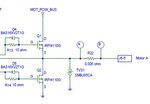
I'm trying to control a BLDC motor using the attached circuit. However, MOSFETS burn when I apply full reverse voltage to brake the motor.
The bus voltage is 48V. The inductance of the motor is 0.06mH.
Can you help me figure out what's the problem? Does it have anything to do with TVS?

Thanks in advance
Gorkem
 

Attachments

  • edaboard.jpg
    edaboard.jpg
    21.3 KB · Views: 157

1. What is the dead time between switching of High Mosfet and Low Mosfet?
2. Put snubber capacitance between Drain of High Mosfet and Source of Low Mosfet. About 1uF. I suggest to measure bus voltage during switching and post result here.
3. What is the reason for TVS. Limit voltage?
 

voltage may be OK but you may exceed drain current ... not necessarily only auto induction is producing trouble , you may also consider some delay times between commutations as a cumulative cause ... I suggest to experiment on virtual models of the system (pspice....)
 

voltage may be OK but you may exceed drain current
I have big doubts that without some extra circuit design bus voltage will be OK. At least during switching period induction current will flow to power bus increasing voltage. And I need notice that it is very rough approximation. In real situation parasitic inductions of wires must be considered. Here is good explanation of switching process https://www.mitsubishielectric.com/semiconductors/files/manuals/powermos3_0.pdf

To gsecer. TVS doesn't help you. When load voltage is more than +Vbus, built-in diode of HIGH MOSFET will be conduct, when voltage is low then -Vbus, built-in diode of LOW MOSFET will be conduct. So you should restrict voltage of bus line in switching period.
 

A possible reason is that the bus voltage is driven above safe limits by the energy recuperation.
 

What is motor resistance? When apply reverse voltage on motor runing, current will be i=(Vdc + Em)/(Rm+Rc), where Vdc is bus voltage, Em is electromotive induced voltage (may be slighty below Vdc at nominal speed and no load, say 45V), Rm is motor resistance and Rc, current sensing resistor. Assuming Rm=1ohm, at first time of full reverse voltage applied, current is aprox. 92A, beyond maxim MOSFET current (72A); check with real values. Also at reversing voltage, MOSFET must support a voltage = Vdc+Em, which mean about 93-96V or even more; maxim Vds of MOSFET is 100V, so very probably that conduct to MOSFET burn.
 
What is motor resistance? When apply reverse voltage on motor runing, current will be i=(Vdc + Em)/(Rm+Rc), where Vdc is bus voltage, Em is electromotive induced voltage (may be slighty below Vdc at nominal speed and no load, say 45V), Rm is motor resistance and Rc, current sensing resistor.

You are right. There will be high current. I think that gsecer can look on the torque-speed characteristic of BLDC and determine maximum current during braking mode.
BLDC.PNG
 

If the motor is still spinning you might see double the net EMF
at the FET, on a hard reversal, that you'd see in normal
start-from-zero or free running.

Might try a controlled ramp-to-zero, then ramp-to-reverse
rather than an abrupt full power direction change.
 

You are best to not exceed the motor current rating as well..
Can you drive with zero Volt by shorting Motor with no Voltage applied then remove short then apply reverse voltage in rapid sequence?

The FETs ON resistance ~5 mOhm, if much less than ESR of the motor then most of the energy will be dissipated in the motor., but that may still cause over current in either device, so acceleration/braking control is better to limit average current with PWM.
 

Status
Not open for further replies.

Similar threads

Part and Inventory Search

Welcome to EDABoard.com

Sponsor

Back
Top