Continue to Site

Welcome to EDAboard.com

Welcome to our site! EDAboard.com is an international Electronics Discussion Forum focused on EDA software, circuits, schematics, books, theory, papers, asic, pld, 8051, DSP, Network, RF, Analog Design, PCB, Service Manuals... and a whole lot more! To participate you need to register. Registration is free. Click here to register now.

help ! I cant brake the motor

Status
Not open for further replies.

anotherbrick

Full Member level 4
Joined
Jan 10, 2009
Messages
217
Helped
1
Reputation
2
Reaction score
1
Trophy points
1,298
Location
Istanbul , Turkey
Activity points
3,142
hello forum

I have a 200 W 24 V DC motor

this motor is driving the accu wheelchair of handicapped person

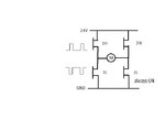
I have built an H bridge with which I PWM the motor for speed control

everything is fine when I PWM the motor ( i.e. when the motor is "motoring" )

however when I lower the PWM level to a lower speed the motor is freewheeling until the wheelchair inertia ( total load of wheelchair and person) is zero and just after that it is motoring with the new PWM value - and this takes about 2 - 3 second which is not wanted by the user

I mean it is not braking ( "generating" )

I want ask why the motor is not braking ( generating ) when I lower the PWM level ?

( I PWM the high side and low side mosfet is fully on )
 

When duty cycle is reduced to the motor, it becomes a generator for a time. If it sees high impedance, it spins freely.

You need to put a temporary load across the motor in order to drop motor speed.

The lower the impedance, the more drastic the speed drop.
 

thank you for the answer

you have said that I should put a load across the motor

the motor is already driven from a 24 V accu through a H bridge

what I want to know why the motor is not recharging the accu for a short time when I lower the duty from %50 to %20 for example ?
 

To recharge the battery "regenerative braking" tyou need to add a charging circuit to dump current back to the cells. It wont hapen automatically!

If you are careful, you can use the H-brige to do the braking for you. The trick is NOT to use PWM as this always injects power into the system but to turn off the top (or bottom) arms of the bridge and turn the other arms on. So instead of the left and right opposing arms being on together, the top or bottom arms are on together instead. This provides a short circuit across the motor which will provide braking action. It wastes power but for the few seconds of operaton, it may be more economical than trying to recover the energy.

Brian.
 

hello again me

I built a controller for electric wheelchair for handicapped

however my H bridge is behaving strange

let me explain what I did ;

the controller according to joystick drives the left and right DC motors
when I drive the wheelchair forward or reverse its OK - the whellchair is moving

however I wrote a code for braking the wheelchair when I bring the joystick to center
I PWM (%15 duty ) the left low side and turn ON (%100 duty) right low side for braking

if I were driving the motor forward the motor does not brake when I leave the joystick
but it brakes when I was driving the motor reverse

this time I PWM (%15 duty ) the right low side and turn ON (%100 duty) left low side for braking

if I were driving the motor forward the motor does brake when I leave the joystick
but it doesnot brake when I was driving the motor reverse

this time I PWM both low sides
and the motor never brakes when I bring the joystik to center

can somebody explain this to me ? how can I brake the motor for both forward and reverse motion ?
 

As far as I understand, the problem is that you are not performing true synchronous PWM, alternating between high and low side switch as required for 4-quadrant H-bridge operation.
 
As far as I understand, the problem is that you are not performing true synchronous PWM, alternating between high and low side switch as required for 4-quadrant H-bridge operation.

hello thanks for answer

I searched google but no success about " true synchronous PWM "
can you give me a link for further explanation about it
 

Synchronous switching means that one switch on each side of the H-bridge is always on (except for a short dead time during switching). This allowas recuperation of motion energy to the DC bus respectively the battery. Finally, the motor can be breaked by simply shorting it, e.g. both low-side switches on.
 
I think regenerative barking is not possible for such vehicle. Speed and duty phases are too low / short to allow a signifiant regenerative to charge a battery. To brake motor, may use shorting motor leads by low sides H bridge switchs (one may be put on and other by PWM switching to controll brake current / force). If current are too high at maxim brake point, need to insert a resistor.
 

I think regenerative barking is not possible for such vehicle. Speed and duty phases are too low / short to allow a signifiant regenerative to charge a battery.
Doesn't sound like a well considered argument. The only reasonable point why regenerative braking won't be possible for an inverter is that the power supply can't sink current, e.g. in a usual AC powered motor inverter. Regenerative braking for a battery powered H bridge doesn't mean more than saving a braking resistor, wheter you save much battery energy or not. I'm quite sure however that a wheelchair operated in a mountainous quarter will take advantage from regenerative braking.

IMHO the typical, rather trivial reason why regenerative breaking doesn't work is that many people don't understand the basic concept of H-bridge 4-quadrant operation.
 
Yes, theoreticaly it's correct but maybe cost or small amount of effective regenerative energy injected in battery lead to cancel this option when balance advantage / cost, increase risk of failures and so on. Theoreticaly many things are possible but when put on the table all advantage / cost / risks may find that answer is no.
 

Hbridge.jpg

As far as I understand, the problem is that you are not performing true synchronous PWM, alternating between high and low side switch as required for 4-quadrant H-bridge operation.

Synchronous switching means that one switch on each side of the H-bridge is always on

sorry I am a slow learner , other than that I didnot understand what you mean

In this picture of my H bridge I PWM 1H and make 2L always ON
however when I reduce the PWM duty there is no regenerative braking - the wheelchair simply freewheels until new steady state speed

what do you mean by "alternating between high and low side" & "one switch on each side of H-bridge always on" ?
( I already make 2L always ON )

in my picture which MOSFETS do I have to alternate ?
 

In this picture of my H bridge I PWM 1H and make 2L always ON
The problem is about understanding pwm operation. When you open switch 1H, the motor current continues to flow due to the motor inductance. Without closing the alternative switch 1L the current flows through the 1L substrate diode, as long as the motor is in an active quadrant. To continue PWM operation during breaking operation, switch 1L must be activated when 1H is off. That's synchronous PWM.
 
Hbridge2.jpg

hello FvM, thank you and danke schoen für deine antworten :)

I draw a picture for "forward motoring"
in this picture are the gate signals correct ?
( you said 1H and 1L must alternate )
did I understand you good ?

one last question :
is the gate signals in the above picture valid for both motoring and regenerative braking (i.e. when reducing the duty below motor EMF )?
or is there a difference ?
 

This is basically a correct synchronous waveform. Some details should be mentioned in addition:
- You'll need a short "dead-time" between off- and on-switching to avoid both transistors conducting simultaneously. For MOSFET, a few 100 ns of dead-time a ususally sufficient, the exact value depends on the speed and timing accuracy of your gate driver circuit. Some gate driver ICs are providing dead-time internally, in other cases you'll need external circuits or a PWM controller that allows to program it.
- PWM control of one bridge side and static switching of the other is one of several possible PWM control algorithms. You'll often try to balance switching losses between both sides by applying PWM control to all 4 transistors. Typical control waveforms are "bipolar" mode, switching both sides complementary and "unipolar", switching both sides phase shifted and resulting in an output ripple of doubled frequency.

is the gate signals in the above picture valid for both motoring and regenerative braking
Basically yes. You can imagine a switched H-bridge as circuit that transforms the bus voltage to a bidirectional source with a voltage between 0 and Vbus. It can both source and sink current, it's voltage is set by the PWM duty cycle and almost independent of the output current magnitude and direction.
 
hello friends,

with your help I could regenerative brake the motor , thank you
this time I have a new problem

I must measure back EMF to know if the motor is rotating or is it blocked

I have found the below schematic for measuring the back EMF

however I am driving the H bridge with synchronous PWM as FvM has adviced to me

now my question ,

I want measure not the driving PWM but the back EMF
at what instant of PWM can I measure back EMF and not the driving PWM voltage ?
is it posible at all ?

thank you
sakatar5.JPG
 

Attachments

  • Hbridge2.jpg
    Hbridge2.jpg
    18.9 KB · Views: 108
Last edited:

If the PWM bridge is active, you can't directly measure the EMF. You can either determine it indirectly from PWM signals and motor current, or by sampling the motor voltage during bridge dead time.
 

I must measure back EMF to know if the motor is rotating or is it blocked
...
at what instant of PWM can I measure back EMF and not the driving PWM voltage ?

yes of course it is easily possible. You have to switch off the pwm drive for a few mSecs so that the motor is freely rotating - not shorted and in brake mode - and measure at this time. The back emf is a direct function of the motor speed - now acting like a generator.
 

hello forum


however when I lower the PWM level to a lower speed the motor is freewheeling until the wheelchair inertia ( total load of wheelchair and person) is zero and just after that it is motoring with the new PWM value - and this takes about 2 - 3 second which is not wanted by the user I want ask why the motor is not braking ( generating ) when I lower the PWM level ?

Hi,
This can be solved by using a motor with reduction gears builtin (motor rpm is high but output rpm will be low) this type of motors comes to a stop very quickly(almost instantly)
 

hello dear friends from all of the world ,

I decided to measure the motor current with acs714 hall effect sensor
however I observed a strange thing ;

when I put the acs714 sensor between the accu and the input of H bridge it measures for example X Amperes
when I put the acs714 in series with the motor ( inside of H bridge ) it measures 3X Amperes

both with same PWM value

why is that so ?
why the motor current 3 times of the current input into the H bridge ?
 

Status
Not open for further replies.

Similar threads

Part and Inventory Search

Welcome to EDABoard.com

Sponsor

Back
Top