Continue to Site

Welcome to EDAboard.com

Welcome to our site! EDAboard.com is an international Electronics Discussion Forum focused on EDA software, circuits, schematics, books, theory, papers, asic, pld, 8051, DSP, Network, RF, Analog Design, PCB, Service Manuals... and a whole lot more! To participate you need to register. Registration is free. Click here to register now.

Fresh attempt at an inductor based voltage booster

Status
Not open for further replies.

boylesg

Advanced Member level 4
Joined
Jul 15, 2012
Messages
1,023
Helped
5
Reputation
10
Reaction score
6
Trophy points
1,318
Location
Epping, Victoria, Australia
Activity points
11,697
Building on my efforts with the charge pump based voltage booster, here is an attempt at converting it to an inductor based one.

Reason....because I know how to invert a standard trany multivibrator such that it still works with a negative voltage input but I was not able to invert other types of multivibrator circuits for what ever reason.

So I am trying to take the best part of my circuit and match it with the inductor part of other circuits.
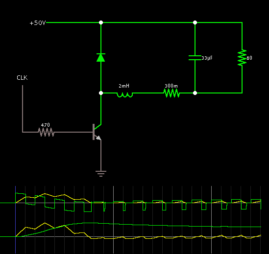
Here it is:


But why does the voltage shoot up to about 20V and then slowly decay back to 11V?

Oh......the load on the output is simply a 100R resistor and an LED.
 

why does the voltage shoot up to about 20V and then slowly decay back to 11V?

At startup, the capacitor is like a short circuit.

This allows surge current to go through most all the components... although it takes a moment to build due to the coil reactance.

Once current has built up, the coil keeps it flowing, causing the temporary high charge level on the capacitor.

This continues through a few cycles, until the action reaches a balance on the coil and capacitor.

That's my explanation from looking at the yellow scope trace below, indicating current through devices.

The upper trace shows coil action.

The lower trace shows capacitor action. Notice how the charge volt level (green trace) resembles your scope image.


The voltage shoots up due to the stored energy in the inductor and then decays to 12V (minus the diode drop) as the energy dissipates. Sounds like normal for that circuit. If you want the voltage to stay near the high value you will need to switch faster, use a larger inductor, or increase the load resistance.
 

Unfortunately the multivibrator outputs are shorted by the 500 ohm resistors and BD139 BE diodes.

You forgot to check if the multivibrator is operating at all before looking at the output voltage.

@BradtheRad: Please notice the difference between a boost and a buck converter.
 

OOOhhhhhhh! After looking at some inductor circuit examples in the applet thing I get it!

With a boost or buck converter a cap and an inductor form a resonant circuit ang it is the job of the multivibrator to give the oscillator current a bit of a prod every now and then to keep it going. I also now understand the difference between an oscillator and a multivibrator.

And that is why my circuit doesn't work, because the inductor has nothing to resonate with.
No, inductor based buck or boost voltage converters do not operate with the inductor and capacitor in resonance. The inductor is used to store energy during its ON time which is transferred to the capacitor during its OFF time which stores the energy and smooths the voltage. The switching frequency is typically far above the resonant frequency of the L and C.

Your circuit does appear to have a capacitor at its output on the right side of the diagram.
 
  • Like
Reactions: FvM

    FvM

    Points: 2
    Helpful Answer Positive Rating
@BradtheRad: Please notice the difference between a boost and a buck converter.

Yes, my converter was a different type from Boylesg.

I brought out one of my experimental switched-coil circuits which had shown the similar effect, with the soaring capacitor level at startup. I have been puzzled until now because I see it regularly.

As it appears, buck converters are more prone to this effect.

In regard to boost converters, I'm finding that the capacitor charge generally rises by steps, incrementally, until it reaches a running level.

I have just taken some time to experiment on a boost type, trying combinations of henry value and frequency, before getting one that resembles the scope trace in post #1.

As a result I admit Crutschow's explanation may apply to Boylesg's converter better than my explanation.
 

Status
Not open for further replies.

Part and Inventory Search

Welcome to EDABoard.com

Sponsor

Back
Top