celegorn
Newbie level 5
Hello,
I am trying to control a DC motor using PIC16F877A through the L298 H-bridge IC.
I programmed the PIC, i set the circuitry up on a breadboard (the PIC, the L298, the power connections etc.) and the motor won't move AT ALL.
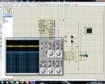
I tried to measure the voltage at the CCP1 pin (RC2 pin) and it is just as it should be, meaning if i set the duty cycle to 255/255 it is ~5V and if i set the duty cycle to 127/255 it is ~2.5V. However, the voltage at the OUT3 pin of the L298 remains ~11V no matter what i do.
The part that really confuses me is although i am measuring ~11V on the OUT3 pin of the L298 (the pin where the motor is connected) the motor doesn't move. I have tested my motor directly to a supply of 12V and it is working perfectly, so it's not the motor.
I have attached the schematic as well as the source code for the PIC, but i really don't think that that's the problem.
####################################### The source code ####################################
######################################### The source code #################################

View attachment pwm.bmp
Feel free to ask questions, i will try to check for replies as often as i can.
Thanks
I am trying to control a DC motor using PIC16F877A through the L298 H-bridge IC.
I programmed the PIC, i set the circuitry up on a breadboard (the PIC, the L298, the power connections etc.) and the motor won't move AT ALL.
I tried to measure the voltage at the CCP1 pin (RC2 pin) and it is just as it should be, meaning if i set the duty cycle to 255/255 it is ~5V and if i set the duty cycle to 127/255 it is ~2.5V. However, the voltage at the OUT3 pin of the L298 remains ~11V no matter what i do.
The part that really confuses me is although i am measuring ~11V on the OUT3 pin of the L298 (the pin where the motor is connected) the motor doesn't move. I have tested my motor directly to a supply of 12V and it is working perfectly, so it's not the motor.
I have attached the schematic as well as the source code for the PIC, but i really don't think that that's the problem.
####################################### The source code ####################################
Code:
int cnt = 127;          //init - pwm cycle

void main() {

TRISB = 0xFF;           // B is input
TRISC = 0X00;           // C is output
PORTC = 0x00;           // Init - C=0
TRISD=0x00;             // D is output
PORTD=0x40;             // D.f6=1 (motor turns clockwise)

ADCON1 = 0x7F;          // all pins digital
INTCON = 0xD0;          // gie i int enabled
OPTION_REG = 0x00;

PWM1_Init(5000);         // pwm freq = 5000hz
PWM1_Set_Duty(cnt);
PWM1_Start();

while (1)
  {

  }
}

void interrupt (void)
{
if (INTCON.INTF)
{
  //motor changes direction on each interrupt:
  PORTD.f7=~PORTD.f7;             // D.f7=1 (motor turns clockwise);
  PORTD.f6=~PORTD.f6;             // D.f6=1 (motor turns counterclockwise)

  PORTD.f0=~PORTD.f0;             // LED on D.f1 changes state on each interrupt
  INTCON.INTF = 0;                // reset int flag
}
}View attachment pwm.bmp
Feel free to ask questions, i will try to check for replies as often as i can.
Thanks
Last edited by a moderator: