Continue to Site

Welcome to EDAboard.com

Welcome to our site! EDAboard.com is an international Electronics Discussion Forum focused on EDA software, circuits, schematics, books, theory, papers, asic, pld, 8051, DSP, Network, RF, Analog Design, PCB, Service Manuals... and a whole lot more! To participate you need to register. Registration is free. Click here to register now.

Transformer 230/12V and buzzer

Status
Not open for further replies.
- - - Updated - - -

Buzzer
KPX1212B

85dB
12V
30mA
3100Hz
with generator

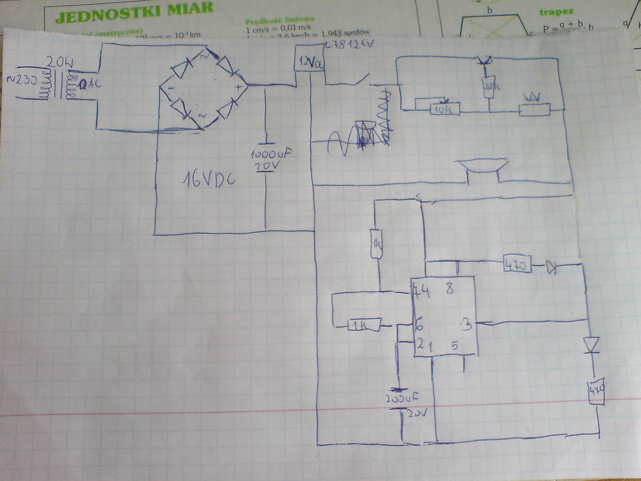
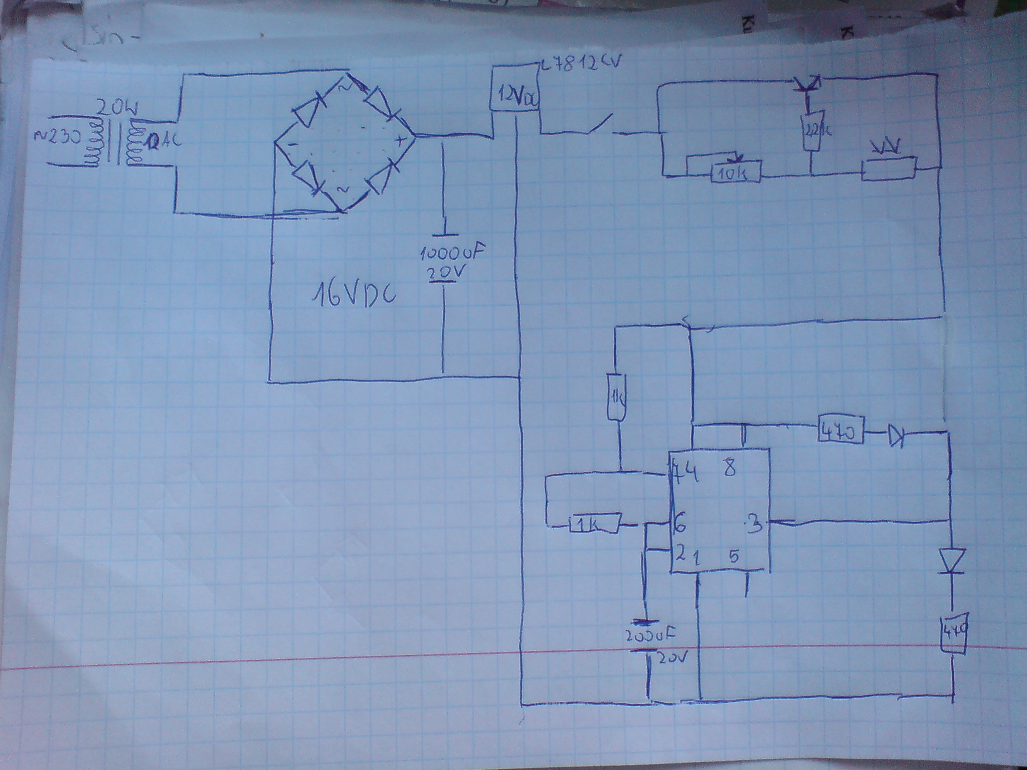
and I want by my system after the fotoresistor will be run when the light beam directed on fotoresistor will be break
 

What provisions for blocking stray flash light , sun light or fluorescent?
What distance between emitter and detector max?
Is this a fixed installation?

How much variation in emitter level do you expect?
How much aging?
Is detector attached to or wired farther away from buzzer ?
Is this being packaged?

- - - Updated - - -

Screen shot 2012-07-23 at 12.08.59 AM.pngScreen shot 2012-07-23 at 12.08.15 AM.png

HTML:
[B]http://www.vishay.com/ir-receiver-modules[/B]

250px-Smitt_hysteresis_graph.svg.png

300px-Ideal_feedback_model.svg.png


**broken link removed**

**broken link removed**

Since this is a simple design..
I will let you connect the dots.

http://www.digikey.com/product-detail/en/SFH 4545/475-2919-ND/2205955
http://www.vishay.com/docs/81869/tshg6210.pdf
1.4V @ 20mA . SO you can drive up to 7 in series from 12V or just 1,2 or 3.
No need to drive it at 200mA.
Use Schmitt Oscillator to drive LEd into RX IR chip. Or use IR LED as a Photo Diode and amplify with CMOS inverter or OA or transistor.
I let you decide how to fit this.
Choose a wall transformer, this will be higher V than rated by 28% with no load. 2xrt(2)
 

Attachments

  • Screen shot 2012-07-23 at 12.08.47 AM.png
    Screen shot 2012-07-23 at 12.08.47 AM.png
    92 KB · Views: 53
  • Screen shot 2012-07-23 at 12.07.44 AM.png
    Screen shot 2012-07-23 at 12.07.44 AM.png
    18.1 KB · Views: 59

Laser will be a light, it will be fixed, i' m not having connected buzzer for the moment, becouse i dont want where i should connect it. I have only transformer, brigde, stabilizer, and timer 555 system with 99% propriety. I don' t know what i should do with part with transistor, potentiometer and fotoresistor.
 

I' ve maked that schematic, with buzzer which after start will ring, and timer 555 with oscilator with 2 LEDs alternately flashing. I want it will run after break laser beam directed on fotoresistor. Is it going to work?

- - - Updated - - -


You have arranged for the buzzer and 555 to receive power by turning on the transistor. This can work, if you can make the transistor conduct more current.

Consider using a PNP transistor, as well as reversing the positions of the photocell and potentiometer.

Per diagram:

96_1343054071.gif
 

yes it may work.. TO improve it, add small electrolytic cap across the V+ to V- on 555 chip >16V > 1uF to filter expect noise current from magnetic buzzer which may be 50% square wave 60mA pk and 30mA average @ 12V

THe transistor after the 12V regulator is a poor current limiter but may work , because it on depends on current gain of transistor and R values. Output current limit will be around 10x bias current from 3 resistor T bias network.. Base current is the voltage / 0.65V from 3R junction to emitter. The emitter is what feeds your circuit V+. This is another location where A cap may be added if far from the 555 and if buzzer is far away, you will want to put another cap across there , taking care to put + on Buzzer + to V+..Choose >= 1uF and >= 16V... any value.alum. electroliytic type is ok here.
The Laser diode is overkill for this design so any photo transistor with dark daylight film filter to block UV and white light from surroundings. Adjust sensitivity of pot in above circuit to control gain of light detector to switch on buzzer. The above circuit may have loss from insufficent gain, since when ON Vce is 0.3V when current gain is only 10x at 60mA for small transistors.

Hfe or Beta may vary by 50% or more depending on Vce. voltage across collector and emitter. Normally it is < 0.3V but increases when Vbe drops below 0.6V.

YOu can make a simple IR 10deg LED work with a much more sensitive detector. In this case in order to drive 60mA peak buzzer, base needs 6mA which is too high for a small phototransistor. If you use darlington photo trans. gain is much higher but buzzer will be quieter with 1.5V drop on transistor. There are simple solutions but hard to communicate how they work to you.

I think you just want your circuit to work, rather than choose a new better design, so it is more complicated to explain what can go wrong.
 

I should to use pnp ir npn transistor now?
But i dont want to use fototransistor, only fotoresistor.
 
Last edited:

Either will work if you reverse buzzer load from pull down to pull up. The key factor is current gain and max current.

The PNP is pulling up the load from gnd..

The NPN would have the load connected to V+ at one end and pull down to ground ( with Vce being the saturation voltage 0.2 if base current is adequate) to apply the same voltage drop across the load as a switch. We call this a common emitter switch.

The preferred transistor types have high current gain when saturated as this degrades rapidly when Vce drops near 0. So overall consider the bipolar transistor as a switch with a current gain of 10 or so.. Small currents maybe x20... big amps.. maybe only x5.. When compared with IGBT switches for big industrial uses, they can get as much as x500
A relay has a current gain from switch contact current to input coil current of about 100 but small reed relays are not as reliable as transistors...

In automotive, they exclusively use MOSFETS as voltage and charge amplifier switches and tend to have a current gain of 100 in normal practice, due to load capacitance currents being switched. A DC car like the Tesla, has over 800 MOSFETs in parallel to drive the motors in order to get the effective series resistance (ESR) of the switches much lower than the effective series resistance of the motors.

This perspective in switching we call ESR switching and is an importance factor when designing switches for high power LEDs and motors from DC. When a system does not have enough gain, several stages of amplification are needed , sometimes called pre-amps or buffers then pre-drivers then drivers depending on the industry and application.

in your design everything is low current, but still is a factor when small signal transistors are used. So choose wisely with assistance.
 
Last edited:

So, can anybody correct and draw my schematic for a high current, and for reaction for fotoresistor to activate circuit after it when the laser or light beam will be broken?
 

So, can anybody correct and draw my schematic for a high current, and for reaction for fotoresistor to activate circuit after it when the laser or light beam will be broken?

The entire 555 circuit becomes the load, as per my schematic in post #45. That schematic is based on an NPN type. I'm going back to that concept because it allows me to make the shortest, easiest change to your layout.

LOAD is a buzzer?

Yes, the buzzer also is the load.

It will be installed in parallel with the 555 circuit, so that both activate at the same time.


Status
Not open for further replies.

Part and Inventory Search

Welcome to EDABoard.com

Sponsor

Back
Top