shom_show
Member level 1
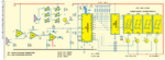
Myself Sumanta Kumar Show is trying to implement a program regarding measurement of Distance through AT89C2051 Microcontroller. The program is as follows -
The corresponding circuit is given in the Attachment. I have burned the program into the microcontroller, but still the circuit is not working and no display is coming in 7 segment display (LTS542). Please check the program and the circuit and suggest me how to rectify the problem. Yours help will be highly appreciated.
Sumanta
Code:
;Program listing:

;$mod51
ORG 0H
AJMP 30H
ORG 0BH ;TIMER 0 INTERRUPT VECTOR; AJMP TIMER0ISR ;Timer 0 Interrupt service routine address

ORG 30H
MOV SP,#60H ;set stack pointer
MOV P3,#0FFH ;set all port 3 bits high to enable inputs also
MOV P1,#03 ;set port 1 to all zeros expect bits 0,1

MOV TMOD,#01100001B ;TIMER 1 - MODE 2 COUNTER,TIMR-0 TO MODE 1
BEG: MOV TH0,#0H ;TIMER REG.0 IS SET TO 0, GIVES 64ms
MOV TL0,#0  ; timer low reg. is also so
            ;TOTAL CYCLE TIME IS 64.6ms ,350m/s gives 0.35mx65=22.5m
            ; up and down 10 metres say! .35 m/ms,.35 mm/us, 1mm per 3 micros
            ; up and down .35/2 mm/us = 1/6 mm/us
            ; VELOCITY OF SOUND IN AIR IS 350 M/S
            ; AFTER 100 TIMES, WE HAVE TO STOP TRANSMITTING FOR A TIME OF ABOUT .1 S
            ; SO WE STOP FOR THIS AMOUNT OF TIME and expect an echo.
mov r2,#25 ; 25 pulses 26 us =.53 ms(343m/s*.5ms=17cm)

pulse: setb p3.4 ;generates 40KHz
mov r1,#5
djnz r1,$
clr p3.4
mov r1,#5
djnz r1,$ ;wait for 13 us
djnz r2, pulse ;20pulses
setb tr0 ;start timer

mov r2,#10
djnz r2,$ ;wait 20 us
check_echo:
jnb p3.6,checktimeout
MOV 40h,TL0 ; read timer count
MOV 41h,TH0
mov r0,40h
mov r1,41h
mov r3,#0
mov r2,#6
call UDIV16 ;divide by 6
mov 40h,r0
mov 41h,r1
mov 50h,#25
disp: call disp1 ; show the value on LED

djnz 50h,disp ; so many times for a visible time limit

jmp beg
checktimeout: mov a,th0
cjne a,#0c0h,check_echo ;upto 4 metres

jmp beg
        ;subroutine UDIV16
        ;16 bit/16bit unsigned divide
        ;input r1,r0 =dividend X
        ;input r3,r2 =divisor Y
        ;output r1,r0 =quottient q of x/y
        ;output r3,r2 = remainder
        ; alters acc,r4-47,flags,dptr
UDIV16: mov r7,#0 ;clear partial remainder
mov r6,#0 ;
mov B,#16 ;set loop count
div_loop: clr C ;clear carry flag
mov a,r0 ; shift the highest bit of dividend into

rlc a
mov r0,a
mov a,r1
rlc a
mov r1,a
mov a,r6 ;... the lowest bit of partial remainder

rlc a
mov r6,a
mov a,r7
rlc a
mov r7,a
mov a,r6
clr C
subb a,r2
mov dpl,a
mov a,r7
subb a,r3
mov dph,a
cpl C
jnc div_1 ;update partial reaminder if borrow

mov r7,dph
mov r6,dpl ; update parital reminder
div_1: mov a,r4
rlc a
mov r4,a
mov a,r5
rlc a
mov r5,a
djnz B,div_loop
mov a,r5
mov r1,a ; put qt. in r0,r1
mov a,r4


mov r0,a
mov a,r7 ;get rem. saved before the
mov r3,a ;last subtraction.
mov a,r6
mov r2,a
ret
         ;16 Bit Hex to BCD Conversion for 8051 Microcontroller

; This routine is for 16 bit Hex to BCD conversion
;
;Accepts a 16 bit binary number in R1,R2 and returns 5 digit BCD in

;R7,R6,R5,R4,R3(upto 64K )
Hex2BCD: ;r1=high byte ;r7 most significant digit

;R2 = LSByte
MOV R3,#00D
MOV R4,#00D
MOV R5,#00D
MOV R6,#00D
MOV R7,#00D
MOV B,#10D
MOV A,R2
DIV AB
MOV R3,B ;
MOV B,#10 ; R7,R6,R5,R4,R3
DIV AB
MOV R4,B
MOV R5,A
CJNE R1,#0H,HIGH_BYTE ; CHECK FOR HIGH BYTE

SJMP ENDD
HIGH_BYTE: MOV A,#6
ADD A,R3
MOV B,#10
DIV AB
MOV R3,B
ADD A,#5
ADD A,R4
MOV B,#10
DIV AB
MOV R4,B
ADD A,#2
ADD A,R5
MOV B,#10
DIV AB
MOV R5,B
CJNE R6,#00D,ADD_IT
SJMP CONTINUE
ADD_IT: ADD A,R6
CONTINUE: MOV R6,A
DJNZ R1,HIGH_BYTE
MOV B, #10D
MOV A,R6
DIV AB
MOV R6,B
MOV R7,A
ENDD: ret
DISP1:
REFRESH: ; content of 18 to 1B memory locations are output on LEDs

; only numbers 0 to 9 and A to F are valid data in these locations

mov r1,41h
mov r2,40h
CALL HEX2BCD
MOV 18H,r3 ; least significant digit
MOV 19H,r4 ; next significant digit
MOV 1AH,r5

MOV 1BH,R6 ; most significant digit(max:9999)

refresh1: MOV R0,#1bh ; 1b,1a,19,18, holds values for 4 digits

MOV R4,#8 ; pin p3.3_ 0 made low one by one starts wth 18

mov r7,#2 ; decimal pt.on 3rd digit from left (2 nd fromright)

PQ2: CALL SEGDISP
deC R0
mov a,r4
rrc a
mov r4,a
jnc pQ2
PV3:
RET
SEGDISP:
mov dptr,#ledcode
MOV A,@R0
ANL A,#0FH
MOVC A,@A+dptr
segcode:
MOV R5,A
ORL A,#03H ; WE WANT TO USE PORT 1 BITS 0 AND 1 FOR INPUT ANLOG

          ; so retain them high
S3: MOV P1,A ; SEGMENT_PORT
MOV A,R5 ;we use p3.7 for the segment ‘a’ of display

RRC A ;so get that bit D0into carry
      ; cpl c
      ; mov p3.5,c ; dec pt is D0 bit that is wired to p3.5

rrc a
mov p3.7,c ;segment ‘a;
S1: MOV A,R4 ; get digit code from r4 00001000

cpl a ;11110111
rrc a ;11111011-1
mov p3.0,c ; output to drive transsitors for digit lighting

rrc a ;11111101-1
mov p3.1,c
rrc a ;11111110-1
mov p3.2,c
rrc a ;1111111-0 yes low makes leftmost digit show msdigit

mov p3.3,c
S5:
S4: ACALL DELAY1 ; let it burn for some time

MOV A,#0ffH ; extinguish the digit after that time

MOV P3,A ; to prevent shadow
s6: RET
ledcode:
DB 7EH,0CH,0B6H,9EH,0CCH,0DAH,0FAH
DB 0EH,0FEH,0CEH,0EEH,0F8H,72H,0BCH,0F6H,0E2H

         ;these are code for the numbers 0 to 9 and A to F

DELAY1: MOV R1,#0ffH
N: NOP
DJNZ R1,N
RET
END
The corresponding circuit is given in the Attachment. I have burned the program into the microcontroller, but still the circuit is not working and no display is coming in 7 segment display (LTS542). Please check the program and the circuit and suggest me how to rectify the problem. Yours help will be highly appreciated.
Sumanta
Attachments
Last edited by a moderator: