chris09
Newbie level 3
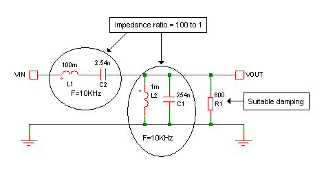
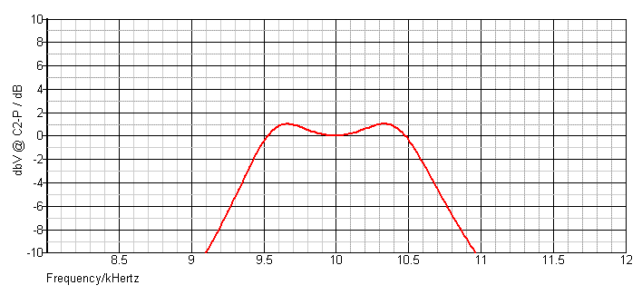
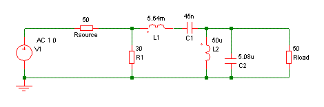
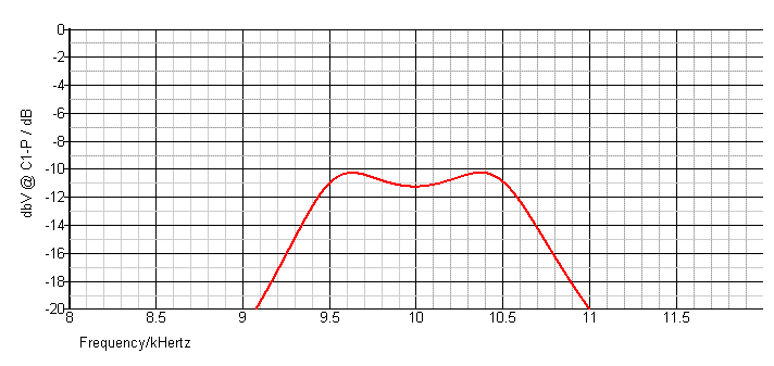
Hi, I want to design a chebyshev bandpass filter of order 3, centre frequency of 10khz and bandwidth of 1khz, I'm also taking a band pass ripple of 1dB. Please I really need help on how to go about the calculations involved in the design (e.g filter transfer function) and how to design this filter itself. The only thing I could get is on the design of a chebyshev low pass filter and I know my way around that. Please I'm in a very tight corner here and I need a little help. Thanks