DFW Z33
Junior Member level 1
Hi guys, I am a new member here. I have been lurking for a while though and really gaining a lot from reading the forums as a non-member. I now have a design issue of my own that I can't resolve and so I figured I'd join and see if yall can help :grin:
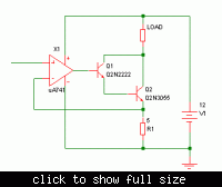
I am designing a variable current source that can deliver between 0 and 1.5A (does not have to be absolutely 0, but the lower the better). I designed a circuit in PSPice that simulates the exact results I am looking for, however my actual circuit is not outputting more than 200mA. Any help would be much appreciated! I will post schematic and specs below.
(I suspect the transistor may be a bottleneck for current flow since it is getting VERY hot)
Specs:
- uA741 opamp
- 12V 1.5A rated wallwart power supply
- A42B331 High voltage transistor
- 1/4 watt resistors (I know they are under-rated for this power level, but I dont mind frying a few while I use them as a test load)
Schematic:

You can ignore the two switches and transistor on the far left of the circuit. They are just there for triggering the circuit when I put it into my larger design. The output current was the same with them just tied to ground.
For anyone wondering, this is going to be a laser diode driver for a 1 Watt diode.
Thanks very much!
John
I am designing a variable current source that can deliver between 0 and 1.5A (does not have to be absolutely 0, but the lower the better). I designed a circuit in PSPice that simulates the exact results I am looking for, however my actual circuit is not outputting more than 200mA. Any help would be much appreciated! I will post schematic and specs below.
(I suspect the transistor may be a bottleneck for current flow since it is getting VERY hot)
Specs:
- uA741 opamp
- 12V 1.5A rated wallwart power supply
- A42B331 High voltage transistor
- 1/4 watt resistors (I know they are under-rated for this power level, but I dont mind frying a few while I use them as a test load)
Schematic:

You can ignore the two switches and transistor on the far left of the circuit. They are just there for triggering the circuit when I put it into my larger design. The output current was the same with them just tied to ground.
For anyone wondering, this is going to be a laser diode driver for a 1 Watt diode.
Thanks very much!
John
