Continue to Site

Welcome to EDAboard.com

Welcome to our site! EDAboard.com is an international Electronics Discussion Forum focused on EDA software, circuits, schematics, books, theory, papers, asic, pld, 8051, DSP, Network, RF, Analog Design, PCB, Service Manuals... and a whole lot more! To participate you need to register. Registration is free. Click here to register now.

Frequency multiplier with low jitter?

Status
Not open for further replies.

Astrid

Full Member level 3
Joined
Jul 11, 2011
Messages
152
Helped
4
Reputation
8
Reaction score
3
Trophy points
1,298
Activity points
2,492
Hello, I have 50MHz clock (sin) and need 100MHz with low jitter.
How?
 

When the clock is high, you want to make the new clock fall back to zero halfway through.
When the clock goes low you want the new clock to go high, then fall back to zero halfway through..

You'll need two one-shot multivibrators to do the job.

Both will be designed to go high for a brief time.

One will be triggered by a rising edge. The other will be triggered by a falling edge.

You must adjust them to fall back to zero after the correct amount of time.

This method will let you have the new clock signal synchronized to the original clock.

-----------------------------

Edited to add:

There may be a way to use a single one-shot, if you can get it to trigger in response to either a rising or falling edge.
 
Last edited:

Hello, I have 50MHz clock (sin) and need 100MHz with low jitter.
How?

Depending on how much jitter you can tolerate, how much jitter exists on the 50MHz clock, how symmetric your 100MHz should be, how much the 50MHz clock can vary in frequency, and how much complexity you can tolerate, here are a few solutions I can think of:
a) Use a PLL. A PLL consists of a phase detector, a compensation filter, a voltage-controlled oscillator, and a clock divider. Using a clock divider ratio of 1/2, the output will be divided by two before being compared to the input, so the output will have twice the frequency.
b) Use a DLL. Instead of a VCO, you have a delay block, which consists of multiple delayed inversions. The 50MHz clock, after several delays, is compared to itself and servo'd into phase. Taking a tap off of the inversions internal to the delay block, will yield signals at 50MHz which are out of phase with each other. If the delay block consists of four internal delays, then each one is 90 degrees out of phase with the one before it (since they all must add up to 360 degrees). Feeding two signals that are 90 degrees out of phase into logic gates (XOR-type) will produce a 100MHz signal.
c) Use a comb generator. The 50MHz clock can be fed to an amplifier which produces lots of distortion. Using a tuned filter, you can select the 100MHz harmonic. Amplifying this will then yield a 100MHz clock.

Hope this helps.
 

Hello, I have 50MHz clock (sin) and need 100MHz with low jitter.
How?

If your signal level is high enough, you could use a double-balanced mixer as a doubler. Depending on your application, you may or may not need a low-pass filter after the mixer to give you a cleaner sine wave.

Ed
 

Now I see your waveform is a sine.

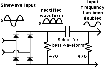
This schematic is a frequency doubler which works with sine waves:

78_1340302079.gif


You'll have to determine whether fast diodes are needed. Also what value capacitor gives you sufficient voltage swings.

You'll have to determine whether its output phase is compatible with your requirements.
 

Dear Astrid
Hi
Do you know what clock does mean ? a sine wave ? i don't think so . anywhere , at first create a low frequency ( will has low jitter ) and then use a class C multiplier .
Best Wishes
Goldsmith
 

OK I will give details,
Primari have rubidium 10MHz frequency normal disciplined with GPS.
From this sinus I do rectangle and over filter and amplifier separate 5th harmonics (50MHz).
Also need 100MHz, and I would like to maintain quality why not use digital multiplier and certainly PLL
 

Status
Not open for further replies.

Part and Inventory Search

Welcome to EDABoard.com

Sponsor

Back
Top