Continue to Site

Welcome to EDAboard.com

Welcome to our site! EDAboard.com is an international Electronics Discussion Forum focused on EDA software, circuits, schematics, books, theory, papers, asic, pld, 8051, DSP, Network, RF, Analog Design, PCB, Service Manuals... and a whole lot more! To participate you need to register. Registration is free. Click here to register now.

Want to know operation of this Schematic

Status
Not open for further replies.
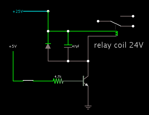
is it a circuit of charge pump relay drive circuit?

I have made a simulation of the middle section.

The capacitors do not have what is specifically called charge pump action. They are exposed to alternating current square waves.

The transistors create push-pull action. This results in current going around an upper loop and a lower loop.

AC goes through the combination of C1 - D1 - D4 - R7.
Notice the diodes both point toward X1. This creates a high positive volt level at X1.

Similarly Y1 is at a low volt level. (Notice the neighboring diodes point away from Y1.)

One is reminded how AC is converted to DC by a conventional diode-bridge power supply.

When the transistors are off, the capacitors block all DC. The right hand section receives no current. (I was wrong about the charge bleeding off when idle. The capacitors acquire a greater DC charge when idle, than they had while the action was going.)

We might wonder why a DC supply is converted to AC, and then back to DC. I believe it must be a safeguard, with the aim to disconnect the relay from all power rails.
 

Actually i wanna use this circuit to operate my relay, would it be advisable? actually i want to operate my relay with the charge pump relay drive technique (for UL safety standard)? can you suggest me any other circuit which can perform charge pump action to drive relay? in my case i want to control my charging cycle of relay coil with the help of microcontroller.
 

actually i want to operate my relay with the charge pump relay drive technique (for UL safety standard)? can you suggest me any other circuit which can perform charge pump action to drive relay?

Your post #8 links to a schematic called 'fig2.bmp'. (5 M bytes)

This circuit does a similar job as the one in post #1, with fewer components.

It has capacitor action which is about the closest thing to a charge pump (since this appears to be important to you).

I have been running a simulation (composed in Falstad's animated simulator at falstad.com/circuit)

The transistors create push-pull AC circulation. There is the upper loop and the lower loop. Square waves go back and forth in the loops, at half the supply V.

Then the capacitors and diodes act the same as a Greinacher voltage doubler.

The relay coil is energized by a volt level which is equal to supply V minus 2 V.

The negative node is above the relay coil, the positive node is below it.

When pulses stop coming from the left, the capacitors lose charge. The load is isolated from the supply rails.

I do not know if this circuit complies with UL safety standards.

I do not know if it will always perform better than post #1 method, in all conditions.

The schematic in post #1 has extra circuitry. The reason may be to reduce the chance of false response in the relay. It is important that the relay not turn off momentarily while it is supposed to be on, nor turn on momentarily while it should be off. If safeguards are not added to stabilize the supply, surges or spikes on the supply rails could cause jittery action in the relay.
 
  • Like
Reactions: jasonc2

    jasonc2

    Points: 2
    Helpful Answer Positive Rating
Thank you so much Bradtherad, I must say you are expert in this, your description really helps me, and yes i want to reduce the chance of false response in relay, and fail safe condition also, i am interested to operate 24VDC relay with this charge pump circuit, Part number of relay is T7CS5D-24, could you suggest me the value of other components?

- - - Updated - - -

Thank you so much Bradtherad, I must say you are expert in this, your description really helps me, and yes i want to reduce the chance of false response in relay, and fail safe condition also, i am interested to operate 24VDC relay with this charge pump circuit, Part number of relay is T7CS5D-24, could you suggest me the value of other components?
 

i am interested to operate 24VDC relay with this charge pump circuit, Part number of relay is T7CS5D-24, could you suggest me the value of other components?

* DC supply can be between 28 and 32 V.

* The zeners should each be rated for 50 to 65 percent of supply V. Together they must add up to more than the supply V.

(If the combined zener V is too low then it will allow unintended bias to flow from the PNP down through the NPN. This will turn on both transistors simultaneously and cause a short circuit.)

* The clock must alternate between sufficiently high V and sufficiently low V (near the DC supply levels), in order to bias the transistors properly.

* The device providing the clock signal must be able to both source and sink current.
 
  • Like
Reactions: jasonc2

    jasonc2

    Points: 2
    Helpful Answer Positive Rating
* DC supply can be between 28 and 32 V.

* The zeners should each be rated for 50 to 65 percent of supply V. Together they must add up to more than the supply V.

(If the combined zener V is too low then it will allow unintended bias to flow from the PNP down through the NPN. This will turn on both transistors simultaneously and cause a short circuit.)

* The clock must alternate between sufficiently high V and sufficiently low V (near the DC supply levels), in order to bias the transistors properly.

* The device providing the clock signal must be able to both source and sink current.

Thanks for the information BardtheRad, please go through the following point.

1) DC supply must be the same as operating voltage of DC relay, is that true? so in my case i want to drive 24VDC relay
2) so according to that DZ1 and DZ2 should be around 18VDC or so ?
3) can you suggest me part no. of transistors,A1,A2 which is best suitable in this circuit?
4) please let me know the value of other component if you can that would be great help for me

and one more thing could you please suggest me the name of free simulation tool for transistor and Op-amp circuit?

Thanks
 

1) DC supply must be the same as operating voltage of DC relay, is that true? so in my case i want to drive 24VDC relay

The DC supply should be 3 or 4 V greater than the relay coil needs.

2) so according to that DZ1 and DZ2 should be around 18VDC or so ?

I am using 16 V zeners.

3) can you suggest me part no. of transistors,A1,A2 which is best suitable in this circuit?

I see them passing 500 mA at 50 percent duty cycle. Medium power general purpose.

4) please let me know the value of other component if you can that would be great help for me

and one more thing could you please suggest me the name of free simulation tool for transistor and Op-amp circuit?

The Falstad simulator can export a clickable link which will create my simulation on your computer. It opens the falstad.com website. Click Yes when it asks to install the java applet.

You can click the switch to turn it on and off. You can change component values.

https://www.falstad.com/circuit/#$+...95+32.73390607896142+0.1636695303948071+2+-1
 

That simulation really helps, but i have following query
1) In this simulation you have set CLK frequency 14V and 60Hz, but in my case i am controlling this signal via IO pin of microcontroller, it only generate 5VDC output, let me know the ideal frequency in this case?
2) Can you suggest me the part number of A1 and A2 because i am unable to identify specific part number, linear technology opamp is most suitable priority.
3) did you designed that simulation by considering 24VDC relay? i am using T7CS5D-24 relay.
4) it would be great if you guide me to identify component value in cosideration of 24VDC relay?

- - - Updated - - -

That simulation really helps, but i have following query
1) In this simulation you have set CLK frequency 14V and 60Hz, but in my case i am controlling this signal via IO pin of microcontroller, it only generate 5VDC output, let me know the ideal frequency in this case?
2) Can you suggest me the part number of A1 and A2 because i am unable to identify specific part number, linear technology opamp is most suitable priority.
3) did you designed that simulation by considering 24VDC relay? i am using T7CS5D-24 relay.
4) it would be great if you guide me to identify component value in cosideration of 24VDC relay?
 

Here is a revised layout.

The 5V clock drives a small-signal transistor, which drives the medium-power transistors. The transistors can be general-purpose type as long as they are rated to withstand the volt levels.

The relay is shown. I guessed as to its coil resistance and turn-on current. A snubber diode is added because it is good practice, even though the relay is not exposed to sudden current changes in this circuit.

Click the switch at left, to see the delayed action at the relay.

https://www.falstad.com/circuit/#$+...+46.873159553587975+0.46873159553587984+1+-1

-------------------------

Since you are using a microcontroller, there is an easier way to control the relay without elaborate circuitry. Just use a single transistor.

Try this link:

https://www.falstad.com/circuit/#$+...08+272+208+0 d+272+208+272+112+1+0.805904783

The capacitor is included to create a small time delay. Or the time delay can be done in programming.

The switch is included at left so you can observe the action as the microcontroller turns the signal on and off.

- - - Updated - - -

69_1341499955.png
 
Last edited:

Here is a revised layout.

The circuit doesn't meet the requirements for fail-safe operation achieved in the original circuit. A push-pull driver with e.g. 30 V swing will be required.
 

The circuit doesn't meet the requirements for fail-safe operation achieved in the original circuit. A push-pull driver with e.g. 30 V swing will be required.

Right. Thank you.

The specs say the relay has to open if any component fails. Per post #13:

following are the condition where relay should not operate

1) when microcontroller fails
2) When microcontroller I/O pin goes in continous high stage
3) When microcontroller software gone hang or something wrong with software
4) when short circuit happen in relay drive section or related parts

Actually i got the information from UL that if we can control the relay with the help of charge pump concept we can satisfy above conditions, but i dont know how to develop a charge pump relay drive circuit.

The simple one-transistor method does not qualify.

The relay will stay closed if the controller stays high, or if the transistor fails in short-circuit mode.

That makes the simple one-transistor diagram an example of how NOT to comply with UL specs.
 

Thanks for the updated simulation, but do you think it serve my purpose what i am looking for?

I want to operate the relay by microcontroller only, if something goes wrong with microcontroller hardware or in built software at that relay should not connect, thats the main basic aspect of UL 1998 and UL 353 standard.

Can you suggest me how would i satisfy this conditions?

I thought the shcematic i have posted its a charge pump relay drive circuit and it might serve my purpose?

Please help me out.....

Hello i am unable to simulate following circuit on falstad, can you please help me to identify the problem? suggest me if is there any thing wrong with circuit it self

https://www.falstad.com/circuit/#$+...4+0+35+5.0+0.2+0+-1 o+0+64+0+35+5.0+0.1+1+-1
 
Last edited:

Awaiting for your response friends
 

Hello i am unable to simulate following circuit on falstad, can you please help me to identify the problem? suggest me if is there any thing wrong with circuit it self

I re-arranged wires so the simulator could recognize nodes correctly. I removed overlaps in the wiring.

The link below shows how the relay stays closed as long as the mosfet receives clock pulses. In that respect it operates as you intended.

However the relay will remain energized if the mosfet fails as a short-circuit. The relay is supposed to open if anything goes wrong. In this respect your new circuit apparently does not meet the fail-safe specs.

https://www.falstad.com/circuit/#$+...+12.0+12.0+0.0+0.5 o+0+64+0+35+40.0+6.4+0+-1

It has become clear why the UL recommends that your relay driver use a charge-pump. The idea is that the capacitors will respond to AC, but will not pass DC. Hence the AC must continue operating, or the relay loses power.

Thanks for rearranging the wires, i have seen the simulation but why other relay is not opearting at all (downword relay) ?
Whats the diffrent between Post 34 and Post 29(1st circuit) charge pump circuit?
Could you please guide me which one is more suitable as per fail safe standard and UL criteria?
Why we are using 28VDC to operate 24VDC relay (Post 29 1st circuit)?
Can we design such circuit which is operating on 24VDC power supply to drive 24VDC relay ? if its possible in our current circuit (Post 29 1st circuit), can you modify and share falstad link with me?
And if i want to operate 12VDC relay by 24VDC power supply sources, what are the necessary changes needs to be done in Post 29 1st circuit ?
Please let me know the part number of Post 29 1st circuit, so i can implement that circuit on bread board and check it practically.

I really appreciate your help....


Awaiting your response friends

- - - Updated - - -

Thanks for rearranging the wires, i have seen the simulation but why other relay is not opearting at all (downword relay) ?
Whats the diffrent between Post 34 and Post 29(1st circuit) charge pump circuit?
Could you please guide me which one is more suitable as per fail safe standard and UL criteria?
Why we are using 28VDC to operate 24VDC relay (Post 29 1st circuit)?
Can we design such circuit which is operating on 24VDC power supply to drive 24VDC relay ? if its possible in our current circuit (Post 29 1st circuit), can you modify and share falstad link with me?
And if i want to operate 12VDC relay by 24VDC power supply sources, what are the necessary changes needs to be done in Post 29 1st circuit ?
Please let me know the part number of Post 29 1st circuit, so i can implement that circuit on bread board and check it practically.

I really appreciate your help....


Awaiting your response friends
 

Thanks for rearranging the wires, i have seen the simulation but why other relay is not opearting at all (downword relay) ?

Ah, well, uh... the other relay has no complete circuit sending current through it.

I did not try to revise that part of your schematic.

Whats the diffrent between Post 34 and Post 29(1st circuit) charge pump circuit?

Post 29, 1st circuit, is a more complex way to deliver power to the relay. This is a safeguard which presumably will halt power to the relay coil in the event of any malfunction in the circuit.

It has taken me a while to realize that is the importance of the charge-pump aspect. It is part of the circuit action which needs to continue as long as the relay is supposed to be closed.

Could you please guide me which one is more suitable as per fail safe standard and UL criteria?

The schematic in post #1 is the most elaborate. It probably has more safeguards built in than any other we've discussed in this thread.

If you are working on a project which is intended to be installed where people are living, then I have to urge you to become familiar with all UL specs in this application.

If your project has to do with opening and closing fuel valves, then it is crucial that you exercise every precaution, on behalf of real people whose lives might be at stake. I personally know one family who had to get out of their beds and leave their house in the night, dazed and groggy because in their sleep they had started inhaling gas fumes coming from a faulty furnace.

Why we are using 28VDC to operate 24VDC relay (Post 29 1st circuit)?

I started with a lower supply V and worked my way up until the relay was getting 24 VDC. The supply needs to be high enough to overcome a drop of a few volts, due to going through components.

Can we design such circuit which is operating on 24VDC power supply to drive 24VDC relay ? if its possible in our current circuit (Post 29 1st circuit), can you modify and share falstad link with me?

In the US it is common to find a 30 or 32 VAC transformer installed in the basement somewhere, to operate the doorbell, thermostats, furnace, etc.

Most likely you can hook up to that, and convert it to DC for your relay.

And if i want to operate 12VDC relay by 24VDC power supply sources, what are the necessary changes needs to be done in Post 29 1st circuit ?
Please let me know the part number of Post 29 1st circuit, so i can implement that circuit on bread board and check it practically.

You would use a DC supply which is a few V higher than the V rating on the relay coil.

You would use zener values which together total a few volts higher than your DC supply.

You may have to regulate your DC supply. Because if you use the 32 VAC power, and rectify it, and add a filter capacitor, then the output could soar to 44 V unregulated with a light load.
 

Ah, well, uh... the other relay has no complete circuit sending current through it.

I did not try to revise that part of your schematic.

Can you please let me know whats wrong with other relay circuit? Whats the logic to connect 2 relay with One MOSFET and Transistor?


Post 29, 1st circuit, is a more complex way to deliver power to the relay. This is a safeguard which presumably will halt power to the relay coil in the event of any malfunction in the circuit.

It has taken me a while to realize that is the importance of the charge-pump aspect. It is part of the circuit action which needs to continue as long as the relay is supposed to be closed.

You mean to say Post 34 and Post 29(1st circuit) both are similar? if i would like to use any one of them which you would recommend?

The schematic in post #1 is the most elaborate. It probably has more safeguards built in than any other we've discussed in this thread.

If you are working on a project which is intended to be installed where people are living, then I have to urge you to become familiar with all UL specs in this application.

If your project has to do with opening and closing fuel valves, then it is crucial that you exercise every precaution, on behalf of real people whose lives might be at stake. I personally know one family who had to get out of their beds and leave their house in the night, dazed and groggy because in their sleep they had started inhaling gas fumes coming from a faulty furnace.

Even personally i feel that Post #1 circuit is more perfect as per UL standard, but i am unable to identify specific Op-amp part number, could you please create Post #1 circuit in Falstad simulator? and yes i am going to control boiler by this Charge Pump circuit, thats why UL standard is mandatory.


I started with a lower supply V and worked my way up until the relay was getting 24 VDC. The supply needs to be high enough to overcome a drop of a few volts, due to going through components.


In the US it is common to find a 30 or 32 VAC transformer installed in the basement somewhere, to operate the doorbell, thermostats, furnace, etc.

Most likely you can hook up to that, and convert it to DC for your relay.

I want to drive 24VDC relay with 24VDC power supply, how can i do that? because i have only 24VDC and 24VAC power supply available in my module, and i cant accomodate another 28VDC power supply.

You would use a DC supply which is a few V higher than the V rating on the relay coil.

You would use zener values which together total a few volts higher than your DC supply.

You may have to regulate your DC supply. Because if you use the 32 VAC power, and rectify it, and add a filter capacitor, then the output could soar to 44 V unregulated with a light load.

Can you post a Falsatd simulator circuit which has 12VDC relay and it operates on 24VDC power supply?

And one more thing i am looking for a transformerless solution which can convert 24VAC into 24VDC, do you have any idea about that? any suggestion

- - - Updated - - -

Ah, well, uh... the other relay has no complete circuit sending current through it.

I did not try to revise that part of your schematic.

Can you please let me know whats wrong with other relay circuit? Whats the logic to connect 2 relay with One MOSFET and Transistor?


Post 29, 1st circuit, is a more complex way to deliver power to the relay. This is a safeguard which presumably will halt power to the relay coil in the event of any malfunction in the circuit.

It has taken me a while to realize that is the importance of the charge-pump aspect. It is part of the circuit action which needs to continue as long as the relay is supposed to be closed.

You mean to say Post 34 and Post 29(1st circuit) both are similar? if i would like to use any one of them which you would recommend?

The schematic in post #1 is the most elaborate. It probably has more safeguards built in than any other we've discussed in this thread.

If you are working on a project which is intended to be installed where people are living, then I have to urge you to become familiar with all UL specs in this application.

If your project has to do with opening and closing fuel valves, then it is crucial that you exercise every precaution, on behalf of real people whose lives might be at stake. I personally know one family who had to get out of their beds and leave their house in the night, dazed and groggy because in their sleep they had started inhaling gas fumes coming from a faulty furnace.

Even personally i feel that Post #1 circuit is more perfect as per UL standard, but i am unable to identify specific Op-amp part number, could you please create Post #1 circuit in Falstad simulator? and yes i am going to control boiler by this Charge Pump circuit, thats why UL standard is mandatory.


I started with a lower supply V and worked my way up until the relay was getting 24 VDC. The supply needs to be high enough to overcome a drop of a few volts, due to going through components.


In the US it is common to find a 30 or 32 VAC transformer installed in the basement somewhere, to operate the doorbell, thermostats, furnace, etc.

Most likely you can hook up to that, and convert it to DC for your relay.

I want to drive 24VDC relay with 24VDC power supply, how can i do that? because i have only 24VDC and 24VAC power supply available in my module, and i cant accomodate another 28VDC power supply.

You would use a DC supply which is a few V higher than the V rating on the relay coil.

You would use zener values which together total a few volts higher than your DC supply.

You may have to regulate your DC supply. Because if you use the 32 VAC power, and rectify it, and add a filter capacitor, then the output could soar to 44 V unregulated with a light load.

Can you post a Falsatd simulator circuit which has 12VDC relay and it operates on 24VDC power supply?

And one more thing i am looking for a transformerless solution which can convert 24VAC into 24VDC, do you have any idea about that? any suggestion
 

Can you please let me know whats wrong with other relay circuit? Whats the logic to connect 2 relay with One MOSFET and Transistor?

If both relays are on at the same time, then you can connect the coils in parallel. You must provide sufficient volt level to turn both on.

If one relay needs to be on while the other is off, then you will need to install an inverter, which can be made from a transistor.

Even personally i feel that Post #1 circuit is more perfect as per UL standard, but i am unable to identify specific Op-amp part number, could you please create Post #1 circuit in Falstad simulator? and yes i am going to control boiler by this Charge Pump circuit, thats why UL standard is mandatory.

This contains the essential portion in post #1:

https://tinyurl.com/8882zvm

I used a 24 VDC supply. This assumes your relay will activate when 21 V is applied to the coil. It's a big assumption to make.

The op amps can be general purpose. You need to use a type that can withstand 24 V at its pins.

The relay activates briefly when power is first applied. More work needs to be done to find a way to prevent this.

I want to drive 24VDC relay with 24VDC power supply, how can i do that? because i have only 24VDC and 24VAC power supply available in my module, and i cant accomodate another 28VDC power supply.

You can build a DC supply powered by the 24 VAC. With luck it will rise to 28 VDC.

It may not absolutely have to be as high as 28 VDC. A relay coil usually activates at a lower volt level than its rating.

Can you post a Falsatd simulator circuit which has 12VDC relay and it operates on 24VDC power supply?

Volt level on the relay can be reduced by doing one or more of the following:

* Reduce bias to the push-pull transistors.

* Use smaller capacitors.

* Increase existing resistor values, or
add resistors somewhere in wires that carry power.

And one more thing i am looking for a transformerless solution which can convert 24VAC into 24VDC, do you have any idea about that? any suggestion

'Full-wave Rectifier with Smoothing Capacitor'

https://www.electronics-tutorials.ws/diode/diode_6.html

This is liable to soar to 33 VDC with a light load. You may need to include a voltage regulator.
 

1) What your suggestion on Post #34 circuit? As per that circuit both relay should connect at the same time it connects in alternate way, like one is ON and other is OFF, i am interested to understand logic of this circuit
2) Post 39 Falstad circuit really helps me to understand the operation of the circuit, but that circuit operates on 400 ohms coil resistance of relay, but in my case i am using T7CS5D-24 relay parts from Tyco, its having 1600 ohms coil resistance, what type of modification i have to do to drive this Tyco relay? One limitation is i can not increase the power supply from 24VDC
3) Can you suggest me any Op-amp part number which is low cost and perform the operation, what we are looking for in Post #34 circuit.
4) This 'Full-wave Rectifier with Smoothing Capacitor' circuit is efficient to generate smooth 24VDC (i mean pure 24VDC)? do you know any such compaq part which perform this action?
 

Status
Not open for further replies.

Similar threads

Part and Inventory Search

Welcome to EDABoard.com

Sponsor

Back
Top