Continue to Site

Welcome to EDAboard.com

Welcome to our site! EDAboard.com is an international Electronics Discussion Forum focused on EDA software, circuits, schematics, books, theory, papers, asic, pld, 8051, DSP, Network, RF, Analog Design, PCB, Service Manuals... and a whole lot more! To participate you need to register. Registration is free. Click here to register now.

how to make connections for 1838 ir phototransistor

Status
Not open for further replies.

rajaram04

Advanced Member level 3
Joined
Jun 17, 2012
Messages
871
Helped
6
Reputation
12
Reaction score
5
Trophy points
1,298
Location
earth
Activity points
7,687
Hello sir
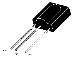
Im using a 1838 IR photo transistor but its not working with simple circuit configuration as i did in tsop series.Now i ve this type of ir phototransistors available only.So please tell me about the simple circuit diagram of the 1838 so as to get proper output when exposed to ir rays.
thanks
 

Im using a 1838 IR photo transistor
Can you provide a link to the datasheet?

I cannot find any photo transistor with 1838 in the part number, only more receiver modules like TSOP1838
 
  • Like
Reactions: asking

    asking

    Points: 2
    Helpful Answer Positive Rating
yes thats it sir its of TSOP series alose but this one is not working like previous ones of big size dimensions & that sensors are not available now in market.i ve today only these sensors with a metal cover on it n very small size , usually im using it in usb players but wen using it in common experiments it was a big failure & no simple circuits as i did in previous are applicable here , im sending the link here please visit sir

https://www.digchip.com/datasheets/parts/datasheet/000/TSOP1838-pdf.php
 

So please tell me about the simple circuit diagram of the 1838 so as to get proper output when exposed to ir rays.
There is an application circuit in the datasheet. If it is for a hobby circuit, you might omit the 4.7uF capacitor and replace the 330 Ohm resistor with a wire link.
 
  • Like
Reactions: asking

    asking

    Points: 2
    Helpful Answer Positive Rating
hmm,sir did everythying including what u told but still not getting result , first time i get so much frustrated to do so cause it was so easy some years back with sensors im showing here & not available now please see below

https://www.lirc.org/ir-audio.html

i used this one as per the circuit digram n was qt simple,but now the available one is harassing me sir , please help & get me the proper biasings for 1838 :(

65_1340174638.png
 

All TSOP-like IR remote control receivers are opreating similarly, they differ however in carrier frequency. Most RC commanders are using 38 kHz, 40 or 36 kHz should be still received with an TSOPxx38 receiver with reduced sensitivity.

All these receivers can be expected to output a pulse sequence when receiving a RC commander signal.
 

ok sir so can you provide a commonly used circuit digram related to a ir sensor or photo transistor please ? i will follow your new configurizwd circuit sir
 

If you are using a microprocessor to receive domestic TV IR signals then the attached JPG file will work. Hardware is simple, all the work is done in software.

If you are using discreet components I cannot help you. I have only ever used a microprocessor to decode TV remote signals

https://obrazki.elektroda.pl/2536185100_1379342258.jpg

You must put a 0.1uF decoupling capacitor across the supply wires of every logic IC in your circuit (including TSOP1838) as close as possible to the IC supply pins.

EDIT: oops... just spotted that this thread is very old :(


thats okk sir thanks a lot , old is gold & a new small information for an unknown is always as new as it was previous :p
thanks once again
 

Status
Not open for further replies.

Similar threads

Part and Inventory Search

Welcome to EDABoard.com

Sponsor

Back
Top