zqbeijing
Newbie level 5
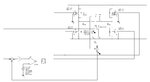
Based on the previous H bridge that I have built with the help from Goldsmith, FvM and andre_teprom (refer to: https://www.edaboard.com/threads/255503/), I designed a h bridge circuit with pwm feedback.
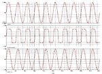
The schematic and simulation results is shown as in attachments.
The result shows the voltage across c1 has a slight phase difference with the current of vccs G1 and reference voltage V2. However i want to perform a power factor correction to make them be more in phase.
Tried RLC Low pass filter with cut off frequency 250Hz but does not show any improvements. Moreover, LPF will involve a large inductor and lead to a very bulky design.
So seeking help with the design of an active PFC. Will anyone give some comments where should I start?
Thanks!