Continue to Site

Welcome to EDAboard.com

Welcome to our site! EDAboard.com is an international Electronics Discussion Forum focused on EDA software, circuits, schematics, books, theory, papers, asic, pld, 8051, DSP, Network, RF, Analog Design, PCB, Service Manuals... and a whole lot more! To participate you need to register. Registration is free. Click here to register now.

Electromagnet Washer Problem

Status
Not open for further replies.

thelaughingfool

Newbie level 5
Joined
May 26, 2012
Messages
8
Helped
0
Reputation
0
Reaction score
0
Trophy points
1,281
Activity points
1,364
I am attempting to build a solenoid and part of it involves building an electromagnet out of a hardware washer. As you might guess, it's not working. I know it's not that I'm using the wrong material or that I don't have enough power or turns in my winding. The washer is made of steel (or at least has enough iron for a permanent magnet to pick it up), and when I tested this on a small steel wrench, it worked acceptably. I used the same wire, power source, and number of turns in each case. It occurs to me that with the washer, there is no pole as there would be in the wrench due to the right hand rule. But I feel like that shouldn't make too much of a difference, and I should be getting some level of magnetism out of the washer. The design I need for the solenoid makes a washer the best option if possible. Can someone tell me what the problem here is and how I can fix it. In case it matters, the washer is about 1/8" thick, has an inner diameter of 1/4" and an outer diameter of 1/2"
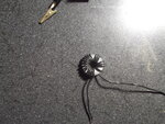
 

Take a photo of the model an post i will try


Regards
LALGPT
 

DSCF0096.JPG
Obviously, the two leading wires are when I hook them up to the power supply. I should also point out that I'm using a 12V power supply. It works fine with the wrench, and adding more power to it doesn't seem to have any effect.
 

You have made a toroid!, this has a totally enclosed magnetic field, hence it does not have any external field so appears not to work. Show us a sketch of what you are trying to do , perhaps we can then help you.
Frank
 

Here is a rough sketch of the solenoid I'm trying to build. For some reason, my scan cut off the indicator that said the tubing in the middle was brass. So I was right in that the poles that would normally form are turned back upon themselves due to the shape. But what if, as I've shown below, I cut away a small wedge of the washer to create a horseshoe shape? This is not only applicable, but practical as well. I need to attach it somewhere (to a non-ferrous material of course). Would that solve the problem I'm having?
SCAN0001.JPG
 

Maybe, it would result in an external field but it's placing would be optimal for aligning something with the edges of the wedge rather than along the axis of the brass rod. A coil wound around the axis would work better.

Brian.
 

solinoid.jpgsolinoid2.jpgsolinoid3.jpgsolinoid4.jpg


Your design is wrong. Try with these figures.

regards
LALGPT
 

As said, wind your coil onto the brass tube. its magnetic field will run down the centre of the tube and will attract other ferrous pieces into it. The field will continue out of the ends of the tube and curl round to enter it at the other end. This magnetic path in free air represents "resistance" to the magnetic field so it will be very advantageous to surround the whole coil with ferrous material, so the only free air path is down the centre of the tube.
Frank
 

Thanks to everyone involved. This will require a substantial redesign, but it should work now. But as long as I have your attention, I'd like to ask two questions:
1) Obviously, the strength of the electromagnet is determined by the number of coils and the current. When I was originally designing this, I came across the idea of have two electromagnet on opposite ends of the ferrous material. The strength in both would vary inversely and in this way I would be able to control the position of the ferrous material. But I have no idea if this is practical or possible. It will take me a while to set up an experiment to test this, so I was wondering if anyone knew about this kind of set up.
2) When I was setting up my washer-with-wedge-cut-out, once it was hooked up to the 12V power supply, it would short out and the battery would begin to smoke. For some reason, I've only noticed this with the washer-with-wedge-cut-out configuration. It doesn't do this with the wrench or the toroid. Can anyone tell me if anything is going on there.
 

1. It is possible but very difficult to set the position accurately, you really need some kind of feedback mechanism that constantly adjusts the two fields to keep the ferrous material stationary. This is why screwed thread and a stepper motor is more commonly used for that application.

2. The effect of inductance will be negligible in deciding the current in a DC circuit so how the coil is wound and on which material is almost irrelevant. What matters is the resistance of the wire as measured in Ohms. The current it passes will be directly proportional to the resistance (I = V/R) and I would guess in your case R is very small and hence I is very large. Assumng the same wire is used, the resistance will depend upon it's length so posibly you used a shorter wire on the washer than on the toroid. Unless you have several hundred turns the resistance will be quite low so a lot of current and power will be used to energize it.

Brian.
 

In my opinion, you are missing the basic concept of electromagnet operation, as lalgpt mentioned.

Electromagnetic force is created in the direction of magnetic field lines. It's acting in a way that the field line are shortened, usually across an air gap. The purpose of the core is to close the magnetic circuit, focussing the field to the zone where you want it to act.
 

Status
Not open for further replies.

Part and Inventory Search

Welcome to EDABoard.com

Sponsor

Back
Top