Continue to Site

Welcome to EDAboard.com

Welcome to our site! EDAboard.com is an international Electronics Discussion Forum focused on EDA software, circuits, schematics, books, theory, papers, asic, pld, 8051, DSP, Network, RF, Analog Design, PCB, Service Manuals... and a whole lot more! To participate you need to register. Registration is free. Click here to register now.

PIC18F & external interupts

Status
Not open for further replies.

grantwr

Newbie level 3
Joined
Jun 3, 2012
Messages
3
Helped
0
Reputation
0
Reaction score
0
Trophy points
1,281
Activity points
1,336
Hi all
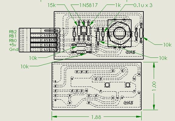
brand new here and really looking for some help. I cant seem to get the pic to respond to an external interupt on pins RB0/Int0, RB1/Int1 or RB2/Int2. The circuit works and displays an initial value on the 7 segment display but an interupt will not cause a change.
To elimenate circuit problems i have stripped it down to just a 1k resistor shorting ground to any one of the input pins. (weak pull ups are enabled).
The main parts of the code are:


Code ASM - [expand]
1
2
3
4
5
6
7
8
9
10
11
12
13
14
15
16
17
18
19
20
21
22
23
24
25
26
27
28
29
30
31
32
33
34
35
36
37
38
39
40
41
42
43
44
45
46
47
48
49
50
51
52
53
54
55
56
57
58
59
60
61
62
63
64
65
66
67
68
LIST P=18F2680          ;directive to define processor
        #include <P18F2680.INC> ;processor specific variable definitions
;***********************************************************************************
    CONFIG      OSC = IRCIO67     ;Internal oscillator block, port function on RA6 and RA7
    CONFIG      WDT = OFF         ;HW Disabled - SW Controlled
    CONFIG      MCLRE = OFF       ;RE3 input pin enabled; MCLR disabled 
    CONFIG      PBADEN = OFF ;PORTB<4> + PORTB<1:0> Config as Dig I/O Pins on Reset
    CONFIG      PWRT = ON         ;PWRT enabled
;i even put a check in for the reset vector
;Reset vector
                ORG     0x0000
        MOVLW   0x0f            ; set counter
        movwf   SEL_counter
                goto    Main            ;go to start of main code
;High priority interrupt vector
                ORG     0x0008
        MOVLW   0x1f            ; set counter
        movwf   SEL_counter
 
;       movf    PORTB,f         ;move PORTB to itself to end mismatch condition ; added but no effect
        bcf     INTCON,INT0IF   ; int0 interupt flag cleared
        bcf     INTCON3,INT1IF  ;clear INT1/RB1 interupt flag
        bcf     INTCON3,INT2IF  ;clear INT2/RB2 interupt flag            
        RETFIE  FAST    ; Return from interrupt, also resets GIE<INTCON:7=1>
Main:
;Initialize OSC
        MOVLW   b'01111010'     ; set osc to 8 Mhz
        movwf   OSCCON
;Initialize PORTA
        CLRF    PORTA           ; Initialize PORTA by clearing output data latches
        MOVLW   0x0f            ; Configure A/D
        movwf   ADCON1          ; for digital I/O
        MOVLW   0x00            ; Value used to initialize data direction
        MOVWF   TRISA           ; Set RA<7:0> as OUTPUTS
        clrf    PORTA           ; to switch OFF all PORTA Outputs - no LEDS lit
;Initialize PORTB
        CLRF    PORTB
        MOVLW   0xf7            ;sets RB<7:0> as inputs with RB<3> as OUTPUTS
        MOVWF   TRISB           ;b'11110111'
        bsf     PORTB,3         ;switch off Neg LED
;Initialize PORTC
        CLRF    PORTC
        MOVLW   0x00            ;sets RC<7:0> as OUTPUTS
        MOVWF   TRISC
        bcf     PORTC,7         ; to switch OFF PORTC,7 Output - no LEDS lit
;Setup registers
        bcf     RCON,IPEN       ;disable Hi/Lo priority interupts - default
        bcf     INTCON2,RBPU    ; PORTB pull ups enabled
        bcf     INTCON2,INTEDG0 ; Int0 interupt on falling edge
        bcf     INTCON2,INTEDG1 ; Int1 interupt on falling edge
        bcf     INTCON2,INTEDG2 ; Int2 interupt on falling edge
 
        bsf     INTCON,INT0IE   ; enable int0 interupts
        bsf     INTCON3,INT1IE  ; enable int1 interupts
        bsf     INTCON3,INT2IE  ; enable int2 interupts
 
        bcf     INTCON,INT0IF   ; int0 interupt flag cleared
        bcf     INTCON3,INT1IF  ; int1 interupt flag cleared - default
        bcf     INTCON3,INT2IF  ; int2 interupt flag cleared - default
 
        bsf     INTCON,PEIE/GIE ; peripheral interupts enabled
        bsf     INTCON,GIE/GIEH ; Global interupts enabled
        
;Set Counter
        MOVLW   0x14            ; set counter
        movwf   SEL_counter
DispLoop:        ; code then goes into a continuous display loop
;converts number in 'SEL_counter' to a form to display on the 7 segment LEDS - all this works fine.


The pic runs and displays '20' (0x14) but nothing will change it. It was initially to be driven from a rotary encoder but i have gradually stripped everything away to try to find the problem without success.
other releveant info - 1st project with PIC18F, 4th project total, 16f84 & 16f628, only familiar with assembly code.
can anyone see where i am going wrong?
thanks
grantwr
 
Last edited by a moderator:

Hi,

Its nice to see well written code with plenty of comments added.

You are very close to the problem, just amend the three lines of your code as below and it interrupts ok.


Code:
 bSf     RCON,IPEN       ;ENABLE  Hi/Lo priority interupts - default
 ;       bsf     INTCON,PEIE/GIE ; peripheral interupts enabled
  bsf     INTCON,GIEH ; Global interupts enabled


Suggest you also show the Low priority vector at 0x018 incase you accidentally send something there.
Unlike the High priority when 'context' saving is done automatically, you have to context save in the low priority.
Code:
		ORG	0x0018

		movff	STATUS,STATUS_TEMP	;save STATUS register
		movff	WREG,WREG_TEMP		;save working register
		movff	BSR,BSR_TEMP		;save BSR register

;	*** low priority interrupt code goes here ***


		movff	BSR_TEMP,BSR		;restore BSR register
		movff	WREG_TEMP,WREG		;restore working register
		movff	STATUS_TEMP,STATUS	;restore STATUS register
		retfie
 

Thanks wp100
(& apologies to bigdogguru - i missed reading that bit)
I tried the changes - btw the peripheral interupts line was just grasping at straws.
when connected back to the rotary encoder, only the switch on RB0 now causes a change in output giving a 31 on the display ( and only intermittently). the rotary part, channels A & B on ports RB1 & RB2 are still totally inactive. A multimeter shows these changing from 0 to 5v as it is rotated.
Can you expalin why enabling high priority should have been a cure. I thought reading the manual that disabling priorities would have worked the same if i didnt need hi & low priority interupts.
still need ideas for a fix!
thanks again
grantwr


Hi,

Only simulated RB0 last night, but just tried all three ports with a simple switch and they do work ok.

What is the speed of your encoder, very fast ?

Couple of things you can try.

If you are using a Pickit or similar programmer have you used the Debugger feature so you can use the single step and breakpoint functions to 'see' your system running ?

What happens if you use simple switches on RB1 and RB2 - are they recognised ok ?

If not, you could try a basic test on the ports RB0-2, just set three switches up, turn off your interrupts, just use the btfss instruction to test each port, if activated turn on a led on another port etc.

Although you say you get +5v ok on your meter from the encoder sometimes the internal pull ups are not enough for some devices and something like an external 10k pull up resistor may be needed.
 

Can you expalin why enabling high priority should have been a cure. I thought reading the manual that disabling priorities would have worked the same if i didnt need hi & low priority interupts.
still need ideas for a fix!


Hi,

The Pic interrupts can be confusing, despite searching have yet to find a good tutorial which details anything other than very basic stuff.
Perhaps BigDogGuru might know of one that will help you ..?

Have tried your program using a motor encoder as input and it does seem to work, though think you might be better using RB4-7 to 'detect any change' for the encoder inputs.

Also you need to set up your ISR routines correctly to avoid overwriting things.

Have a look at the Template file for your chip and see where the High ISR code is placed
c\.. Microchip\MpasmSuite\Templates\Code\pic18f2680
 

Re: PIC18F &amp; external interupts

Hi.
the encoder speed is slow, hand turned knob.
I am using a JDM programmer, very basic and low cost.
I didnt use switches but did turn on the pullup resistors, then tried shorting RBO - RB2 to ground via a 1k resistor - no effect.
I will test each port tonight as you suggest, to make sure the ports are working.
The weak pull ups where only set for testing, Encdr.jpg I have attached a piece of the diagramm to show the circuit and also the component layout.
grantwr

- - - Updated - - -

Hi
RB4-RB7 was to be used for inputs from two more rotary encoders when i get this bit working. The idea was for telescope controller - two encoders on the telescope feed angular postion while the 3rd encoder is used for selecting the co-ordinates of a guide star. the processed output is fed to 7 segment red displays for easy viewing in the dark.
I did use the microchip template for placement.
grantwr
 

Hi,

That seems an interesting project.

Have just tried the ISR on my 18F4520 hardware to confirm what the simulation showed.
Used manual switches on the internal pull ups and all works fine as you can see.

However thats only acting as a simple two channel counter, for your needs you need to do a little bit more to the data.
Assume you have seen site like these ?
http://www.engr.mun.ca/~dpeters/6806/postings/RotaryEncoder.pdf
http://digital-diy.com/swordfish-example/268-external-interrupts-interfacing-a-scroll-wheel-switch.html

As to why your hardware is not working, what is the exact type of encoder you are using ? - that diagram does not show what positve supply is used , it is +5v ?

Think you are lucky your JDM is programming that chip, could never get them to work for me.
If you intend to do some work on Pics then, as you can program the 18Fs already, either make a simple Pickit2 clone or preferably buy a ready made Microchip Pickit2 or Pickit3 programmer, its money very well spent.
 

Attachments

  • 2012-06-04 002.JPG
    2012-06-04 002.JPG
    225.4 KB · Views: 49

Status
Not open for further replies.

Part and Inventory Search

Welcome to EDABoard.com

Sponsor

Back
Top