Continue to Site

Welcome to EDAboard.com

Welcome to our site! EDAboard.com is an international Electronics Discussion Forum focused on EDA software, circuits, schematics, books, theory, papers, asic, pld, 8051, DSP, Network, RF, Analog Design, PCB, Service Manuals... and a whole lot more! To participate you need to register. Registration is free. Click here to register now.

why we can't use all power of rectified voltage

Status
Not open for further replies.

baby_1

Advanced Member level 1
Joined
Dec 3, 2010
Messages
415
Helped
1
Reputation
2
Reaction score
1
Trophy points
1,298
Activity points
4,277
Hello
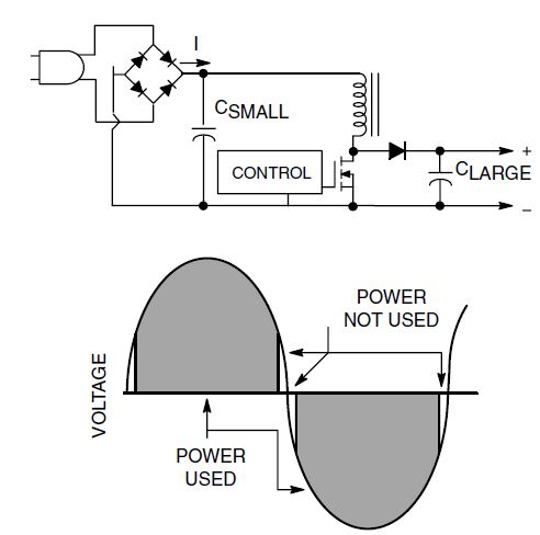
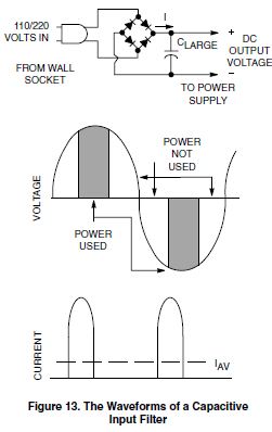
why according this picture we can't use all power of rectified voltage?why in this picture in some part of input signal we can use the (Power not used)?
53_1338540536.jpg
 

Dear baby-1
Hi
I think you are referring to the reactive power due to the Rectifier with capacitive load , right ? if yes , is your problem that why we should use a PFC after that ?
Best Wishes
Goldsmith
 

That's a pretty lousy figure. Check this image from wikipedia:

**broken link removed**

In red you can observe the output voltage.

In the negative slope parts it means that the output voltage is greater than the input AC voltage. Hence the diodes are not conducting. The output slope decreases slightly as the capacitor discharges through the load.

In the positive slope parts it means the capacitor voltage was lower than the input AC voltages, so the diodes conduct and the capacitor is charged.

Bottom line: only during those intevals of time that the diodes are conducting you are effectively transferring power from your AC source to your DC feed circuits.
 
  • Like
Reactions: baby_1

    baby_1

    Points: 2
    Helpful Answer Positive Rating
Hello
yes dear goldsmith i want to use PFC for my SMPS circuit.
Thanks etmabreu
could you tell me why this below circuit have more advantages of before circuit that i uploaded?because rectified and capacitor are fix and
56_1338545052.jpg
 

That is a simplified diagram of a switched mode power supply (SMPS). First, realize the MOSFET is acting as a simple switch. When the MOSFET is conducting you build up a current in the inductor. In a perfect world the current would increase linearly with time. If you have current flowing in the inductor, then you have energy stored in the inductor (P = 0.5 * L * I^2). If you suddenly cut the mosfet, the current in the inductor will flow through the diode to the capacitor (and load). This will charge the capacitor to a certain voltage.

The difficult part is to control the MOSFET properly so to get a stable voltage at the output. That voltage will depend mainly on the duty-cycle of the MOSFET on/off times.

As a final remark, unlike the previous circuit, this relies on a constant energy store/energy transfer idea.
 

Thanks etmabreu
i know how it works.i only want how it has more better that the previous circuit that you explain to me .how it use most of input energy?
 

Hi Again
Did you understand , that why the rectifier with capacitor can create reactive power really ? if yes , i think you can analyze it simply .
The boost converter isn't enough . you should use a line filter before it . this line filter will take an integral from the current wave shape , thus the current through your load will be sinusoidal . ( cos phi , can be exactly 1 ).
Best Luck
Goldsmith
 
  • Like
Reactions: baby_1

    baby_1

    Points: 2
    Helpful Answer Positive Rating
Yes goldsmith
i read a lot about the Complex and reactive power last week and i know how can i use active PFC IC to compensate the line attenuation. i only wana know why in the second picture the we can use most of the input power instead of first one.
 

With this question , now i'm sure that you didn't understand it correctly .
Anywhere , let's analyze it , if we don't use any PFC , we will have just a bridge , rectifier and a capacitor . when the capacitor be full of charge the diode will going to be off . ok ? so , the current will be un sinusoidal , and it means that V*I isn't a sine wave . and according to the Fourier series we will have many harmonics in each un sine wave , ( many sinusoidal harmonics ) .
Hence , the cos phi won't be one . so , we have to improve the shape of current . but how ? it is simple , a line filter before the rectifier and then a boost converter after rectifier . the shape of current will be alike with a triangular . but not a usual triangular wave . triangular*sine . thus the line filter will take an integral from that and it will be a sine wave .
Hence at the 2nd waveform the active power will be higher .
You understand ?
Best Wishes
Goldsmith
 
  • Like
Reactions: baby_1

    baby_1

    Points: 2
    Helpful Answer Positive Rating
Dear goldsmith
Could you tell me with a diagram the step step of the conversion of un sinusoidal signal to a sinusoidal with boost converter such as etmabreu?
Thanks
 

Humm . i can offer you this article . see below please :
https://www.fairchildsemi.com/an/AN/AN-42047.pdf
Or perhaps this one :
**broken link removed**
For more informations , try to read some books , or some other articles or , a simpler way , is googling !!
But if you still have problem , on it , tell me please , thus i can simplify the definitions .
Good luck
Goldsmith
 
  • Like
Reactions: baby_1

    baby_1

    Points: 2
    Helpful Answer Positive Rating
Status
Not open for further replies.

Part and Inventory Search

Welcome to EDABoard.com

Sponsor

Back
Top