Continue to Site

Welcome to EDAboard.com

Welcome to our site! EDAboard.com is an international Electronics Discussion Forum focused on EDA software, circuits, schematics, books, theory, papers, asic, pld, 8051, DSP, Network, RF, Analog Design, PCB, Service Manuals... and a whole lot more! To participate you need to register. Registration is free. Click here to register now.

how to Map ADC pins in PIC24FJ256GB106 ?

Status
Not open for further replies.

nikhilrajg

Member level 3
Joined
Mar 2, 2012
Messages
63
Helped
0
Reputation
0
Reaction score
0
Trophy points
1,286
Location
Manipal,Karnataka,India
Activity points
1,834
Hello everyone,

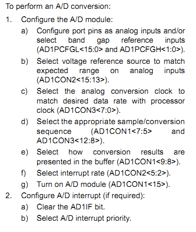
Can anyone explain how the ADC pin of the PIC24FJ256GB106 can be mapped ?

What registers and bits should be set to do this ?

I saw the datasheet of this MCU and got confused. Is it the same way that we map other port pins ?

I know that a port can be mapped by setting its direction register and by setting input or output port or a LATCH (LATbits) can also be used...

But how to map a ADC analog pin ? Which and all registers will be associated with it ? How does it work ?


Please help.

Thanks in advance.

Nikhil Raj.
 

The instructions are provided in page 251 of the datasheet:
93_1338380304.png
 

Hello Tahmid,

Thank you for your reply.
In the code I found these lines..

Code:
AD1CHS = 0;					// Input to AN0 (potentiometer)
AD1PCFGbits.PCFG4 = 0;		// Disable digital input on AN4 (TC1047A temp sensor)

AD1PCFGbits.PCFG5 = 0;		// Disable digital input on AN5 (potentiometer)

They have enabled AN0 as input for potentiometer. But,, is'nt it necessary to do the same for AN4 i.e.,for Temp. Sensor to be enabled ?? by the way there is no temp sensor on the board.

I want to use AN6 and AN7 which are located as 17th and 18th pins respectively in the PIC. So for my application the other analog pins are not available which has been used for other purposes.
So to take AN6 as input what code should i add ?
I want to retrieve analog format voice through AN6 and process it for ADC conversion.

Looking at the code I think,,, to receive an analog signal it uses 2 pins... Am I correct ???

If so for that I want to use AN7 to disable it as digital input to make it analog if I am not wrong.
so for that is this the correct code ?

Code:
AD1PCFGbits.PCFG6 = 0;
 or
 AD1PCFGbits.PCFG7 = 0;

So please suggest Idea and codes.

Thanks in advance.

Regards.
Nikhil Raj.
 
Last edited:

Writing 1 to a bit in ADPCFGx, makes that corresponding channel digital. Writing 0 makes it analogue.

So, you want AN6 and AN7 to be analogue.

So, first let's make all channels digital:
Code:
AD1PCFGH = 0x0003;
AD1PCFGL = 0xFFFF;

Now, PCFG6 and PCFG7 must be cleared.
Code:
AD1PCFGLbits.PCFG6 = 0;
AD1PCFGLbits.PCFG7 = 0;

So, you have configured AN6 and AN7 as analogue and all other channels as digital.

AD1CHS is used to select the channel from which reading is to be taken. So, since reading must be taken for both AN0 and AN4, first AN0 is read and then AN4 is read. So, first AN0 is selected for reading by writing 0.
You can find the AD1CHS0 register in page 256 of the datasheet.

For ADC, go through this reference manual thoroughly. It explains everything thoroughly.
https://ww1.microchip.com/downloads/en/DeviceDoc/39705b.pdf

Hope this helps.
Tahmid.
 
hello Tahmid,

Thank you. I understood this somewhat,, but its really confusing. I am getting confused with the register names and its bits. It is getting changed in every line in the stack code. But whatever I will go through the data sheet again and again to clear it.


I have designed a web page to record the voice. Even I have added a button. I want the voice to be recorded when the button is clicked on the web page. Quite similar to the LED buttons (when they are clicked on the web page they will toggle on the development-board).. SO for that we have used latches..

But as in this case I have enabled as analog pin,, is there anything that acts as a LATCH ?? Fromn the datasheet,,

SAMP: A/D Sample Enable Mode Mode bit
1 = A/D Sample-and-Hold amplifier is sampling
0 = A/D Sample-and-Hold amplifier is holding
When ASAM = 0, writing ‘1’ to this bit starts sampling. When SSRC<2:0> = 000, writing ‘0’ to this bit
will end sampling and start conversion.

So is it the one which I can use it as LATCHES ??
How to initialize it and how to use it ? I don't know the exactly method to do that. Please help.

Thank you.
Nikhil Raj.
 

Hello tahmid,

Do you have any idea that how to make the analog pins active upon clicking a button on the web page ? I mean when the button is clicked the analog pin should take in the data ..

Thank you.
nikhil
 

Status
Not open for further replies.

Similar threads

Part and Inventory Search

Welcome to EDABoard.com

Sponsor

Back
Top