Continue to Site

Welcome to EDAboard.com

Welcome to our site! EDAboard.com is an international Electronics Discussion Forum focused on EDA software, circuits, schematics, books, theory, papers, asic, pld, 8051, DSP, Network, RF, Analog Design, PCB, Service Manuals... and a whole lot more! To participate you need to register. Registration is free. Click here to register now.

Confused about how to calculate effective power/voltage/current of a pulse wave

Status
Not open for further replies.
Re: Confiused about how to calculate effective power/voltage/current of a pulse wave

My doubt is about applying the RMS specific calculation to power quantities, squaring instantaneous power values. I don't see a technical relevance for it, because power already represents squared magnitude (current, voltage, sound pressure, whatsoever) values.
It makes sense when power is being transduced into some other signal in a linear fashion, and you which to know the RMS of the resulting signal, not its average power. In these cases, RMS is interesting because for AC waveforms it is also the standard deviation, which is often of interest.
 

Yes it is complicated, the problem is not how to calculate the power consumed, the problem is which one is the correct one and correct way in calculating.
I didn't find it complicated in battery powered radio applications yet. An oscilloscope with math capabilties is a versatile tool for the measurements. If you want to measure average current with a multimeter, it may be helpful to add filter capcitors to reduce the variance of samples.
 

FvM
Strange that you say that. None of the reply here answered my question and you say "I didn't find it complicated in battery powered radio applications yet. An oscilloscope with math capabilities is a versatile tool for the measurements"
So please tell me which one of the instruments say the truth?
 

In fact, mtwieg gave the answer already in post #6. To determine average power consumption of a device supplied with constant voltage, you need to measure the average current. But you already told, that the oscilloscope is only showing a kind of simulation with a pulse generator, so it doesn't tell about XBee power. And it's not clear how the other instruments are connected in the real measurement and which quantities they are showing. I have been asking for the details in a previous post.

You mentioned a 7 ohm shunt used in your measurement. But the peak current consumed by the XBThe current is measure ee module isn't clear, thus I don't know if the resistance value is suitable. If the peak voltage drop across the shunt doesn't exceed e.g. 0.1 V, it should be O.K.

Here's an example where the supply voltage to a radio transmitter is switched off, similar to the schema in post #39. The curent is measured by a shunt (green trace), you see that the module voltage (yellow trace) is almost constant during operation. In this case, battery voltage (3.6 V) multiply average current gives the average power with sufficient accuracy.


You are not reading all my posts. I uploaded in post 17 the real XBee waveform of the current over the resistor which is 7.3 ohm. Look at the picture which is in the bottom of the other pictures. I wrote under the picture info about that.

look at Post 17

You still talk about average, and I asked you to explain the problem of average using Fourier .. Any precise calculating of the waveform should be using computer and Fourier analyses .. and average will fail there.

In my earlier post, I asked you to tell me the effective voltage of the pulse generated by the function generator. If you answered that question I could solve that matter by myself. The discussion started to go to things that has nothing to do with my questions (like battery charge ..etc)

Ignore the XBee .. You have a waveform shown in the beginning with the measurement of different instruments. Which one is correct. and why.. this is the question .. ignore the XBee ..
 
Last edited:

Thanks for clarification, I didn't notice that the post shows a real measurement, although it's suggested by the different range.

In my opinion, the average value looks trustworthy in this measurement. Did you connect an instrument that measures the same quantity (current average)?

Calculating averages over fourier series makes no sense. Average is just the 0 bin (representing the DC value) of a fourier transformation, all AC components simply cancel. Similarly, in a fourier series decomposition, all sin and cos terms would be ignored when calculatung the average value, only keeping the constant term.

A practical problem of real average measurements may be limited instrument accuracy, e.g oscilloscope input offset. It may be necessary to cancel it by a separate offset measurement.

The offset problem clearly shows in post #3. You have set the function generator to 3V magnitude, 0V offset, 10% duty cycle. So the average value should be 0.3 V, but the oscilloscope shows 80 mV. You also notice a negative baseline. Either if it's an error of the generator, an external error source, or an oscilloscope error, it makes the results pretty unplausible.

If I understand right, there's no digital meter showing a similar quantity (DC voltage respectively average).

P.S.: The two DC voltage measurement sshould show the average voltage of 0.3V +/- some error quantity, assumed they are connected to the same voltage displayed on the oscilloscope, but they both show a values around -1.25V. It can't be related to the function generator output settings, apparently there's a wiring fault in the setup.
 
Last edited:

FvM,

According to the problem description given by Mariwan, I would suggest the below simplified model. You may want to place an arbitrary current waveform instead of the switched load, or you can discuss a pure resistive load as special case.

What am I supposed to discuss, and what am I supposed to do with that schemat?

But isn't it obvious that the integral expression reduces to Pavg = V * Iavg for constant V?

No, I don't see it as obvious for the reasons I gave before.

Ratch


Dear Mariwan,

As my favorite esteemed Physicist Richard Feynman once said, and I paraphrase, "It is better to not know the solution and wonder why, than to know the wrong answer with certainty" Both your Prof. and Wiki are correct but fail to give the reason or wisdom to explain the difference. The problem is simply this;

1. The measurement is only valid if it falls within the range of the instrument. The unit specs. may help understand the error.

M-980T manual Page 6
Changing voltage Area
4V Resolution 1mV±*1.2
Accuracy *±*effectively 5digits
Frequency: 40 Hz to 400 Hz


Your Test: 114 kHz is in ERROR due to exceed the unit operating conditions.

The reason for the error is this instrument is intended for 50/60 Hz and lower signals with harmonics and not Pulsed Zigbee transmitters. The internal LPF is operating on the integration slope of the curve. This integration results in an averaging method rather than the squaring of samples and taking a root of the sum.

Ask your Prof. get the Lab equipment mgr to label all True RMS meters with the MAXIMUM FREQUENCY FOR RMS ACCURACY = ___ Hz . This error applies to high crest factor or low duty cycle signals > the upper frequency of the instrument. A bandwidth limit is often employed to improve SNR and increase the number of digits of resolution in this case 5 digits. In order to improve stability you need a stable voltage on the Sample & Hold prior to the A to D converter. It will then integrate higher frequency noise and thus drift err towards Average Voltage readings.

How to turn a 2 digit meter into a 5 digit meter?
Noise Reduction = √n samples. So 10^6 readings will improve resolution by 3 decades. However accuracy is by design using Band Gap reference diodes in a controlled mini-oven calibrated to 6 digits.

Transient measurements are more difficult to obtain 5 digits of accuracy, but is irrelevant and outside the scope of this discussion. ( no pun intended)

Each meter may have a different LPF cut-off and thus explains your difference in errors on each TRUE RMS D.M.M.


**corrected 5/27 by TS)**
Now consider the pulse errors in calibration readings in this thread for a pulsed DC signal with the ON Duty Cycle D { from 0 to 1 }
These measurement ought to give the identical readings if the signal meets the assumed conditions in the instrument spec. for sampling rate, bandwidth and voltage range in DC coupled mode.

  1. P = Vpk * Ipk * D
  2. P = Vavg * Iavg
  3. P = Vrms * Irms
  4. P ≠ Irms * Vpk & %d.f. { n.b. invalid. }


  1. Notes to above
  2. Easy method using scope or counter to measure D and verify linear square pulses without significant noise or overshoot . Measure Vpk, Ipk at same time and ensure results are stable. Duty cycle D, can be measured with a time interval counter or scope as a fraction from 0 to 1 or 0 to 100%
  3. Valid where instrument is intended to measure average (analog meter, DC mode or Digital Scope in average mode, DC coupled) and signal is verified that both Vpk , Ipk match pulse shape in time and is within frequency range of test instrument ) e.g. dont use microwave on a DMM if it only handles 0~10kHz
  4. Verify bandwidth (BW) of test instrument and make sure the signal being measured does not contain any significant power above this frequency, otherwise error in results can be expected by reduction of peaks towards average rather than instantaneous sample near peak
  5. You cannot multiply measurements for V, I of RMS where one is RMS and the other is average and expect to get true RMS power result. It is statistically invalid. You must either (a) integrate over the entire period and take an average, or (b) use RMS for each V & I which are already a mean result of calculations where the sampling rate must satisfy Shannon's Stability Criteria with a sampling rate >2x the maximum frequency of the Fourier spectrum of the signal. This means a stop band filter must be used or the signal must nbe void of energy above 1/2 the sample rate, otherwise there will be an error when calculating the RMS result ∑V² over the unknown measurement interval. It is best that you understand the duration of this interval as 1/√N applies to significant figures here too.

    Also it is well understood that analog meters are not accurate normally assume Sine waves for AC and convert Peak values measured to display equivalent RMS value for sine only and for DC mode it measures average, so 10% duty cycle give 10% of the DC result as expected only if the frequency is within range of instrument. The error in any counter, scope or DMM readings due to noise will reduce by 1/√N samples. So increasing N cycles with a lower sweep may increase accuracy until Shannon's stability criteria has failed, meaning sampling rate is too slow.

    Say a signal has values of 0 & 1 with duty cycle D=50% , so we expect the result to be 0.5 on average.
    10 samples has a deviation of 1/√10 = 1/3.16 = 0.32 so result is ... 0.5 ± 0.32
    100 samples has a deviation of 1/√100 = 1/10 = 0.10 " " ... 0.50 ± 0.10
    10^6 samples has a deviation of 1/√10^6 = 10^-3 = 0.001 " " ... 0.500 ± 0.001
    10^10 samples has a deviation of 1/√10^10 = 10^-5 = 0.00001 " " ... 0.50000 ± 0.00001


    For example if 10 cycles are measured, you need to take 10 million samples to improve stability from 2 to 5 significant figures. This is based on Shannon's Noise Theorem.


The first three methods should all give the same result for an estimate of RSM power.

DMM discrepancies were due to using the meters outside the range of interest.
The Digital scope is accurate on measuring RMS voltage of the shunt resistor but you must also use the RMS voltage on the load at the same time to get a valid product.

This rate is scaled down when when your time base is 50us total, but will be plenty to exceed Shannon's Law and Nyquist's Theorem for stable accurate readings.

Meters are design to approximate RMS which means a statistical approximate of DC equivalent. But if they integrate the noise with a LPF then, the result will be in error. THis is why TRUE RMS RF power meters for microwave use a thermal heater to measure power ina big 50Ω dummy load and when calibrated, display true RMS from temperature rise calibrated over a time interval adequate to stabilize the result. Heat energy is true RMS power. RMS calculations on digital samples are adequate for accuracy as long as the signal is inside the BW of the measurement system. Otherwise ONLY use Average readings so there. It is easier to calculate the product and less likely to produce RMS errors.

Your attempt to use >100KHz on a DMM rated for 500Hz is more quasi-RMS tending towards Average due to LPF Integration.

The problem is for most instruments, the waveshape is unknown, so the conversion factors cannot be accurate unless it is a sinewave for simple meters and in order to get 5 digits of accuracy , instrument specs must assume a bandwidth limit to eliminate stray noise signal and ground errors.

A better DMM will have a BW limit option. Call your calibration guy and report the issue and ask the Mfg tech support "How to increase the bandwidth"?

If a meter indicates True RMS, do not use it over its intended frequency range. It is designed for 60Hz signals with harmonics. Not Zigbee pulsed power sources.

Also simple non RMS DMM's are not accurate for non-sinusoidal signals because of the different conversion factors for each waveshape. You know the correction factors for assumed sine waveshape fro AVG to RMS, then you can correct the error empirically for a Pulse train or Triangle or other standard wave only to get an estiamte of true RMS.


In Physics, we convert energy from heat to electrical to mechanical based using trusted calibrated meters. However these machines often use simple harmonic motion or sine waves. To answer your dilemma, both your Professor and Wiki are correct, however both omit the assumptions to clarify their answers. Also if meters are not trusted, they should be re-calibrated.

I wish my scope had a Multiply math function for V*I to get the valid equivalent DC power result for power. Does yours? THat would have made it so much easier.

In the meantime, Wiki is correct, but misleading for Electrical Engineers to apply that to RMS Voltage and RMS current to get RMS power and perhaps written by an academic type unaware of this result of interpretation error for EE's

WiKi is not wrong, it is just lacking details for the practise of professional EE students, such as yourself. It is the difference between academic and industrial strength experience in Test Engineering. hahaha
 
Last edited:

As another point besides limited frequency range of true RMS digital meters, the provided RMS measurement is generally an AC measurement in contrast to the DC coupled RMS measurement of an oscilloscope. So apart from general questions about correct measurement method, it should be clear that this measurement can't give the correct result for a DC powered load.

DC (average) measurements shouldn't be affected by limited bandwidth, there must be another explanation for the far-off results.
 

Re: Confiused abou how to calculate effective power/voltage/current of a pulse wave

P.S.: The previous mentioned inequation should be changed into
|Pavg| ≦ Irms*Vrms
because Pavg is a signed quantity

I assume you mean that because it can be a vector quantity and √i = -1 so when Irms is squared it could be a signed vector quantity. :cool: But actually if a negative power would indicate a power source, rather than a power load.
 

I assume you mean that because it can be a vector quantity and √i = -1 so when Irms is squared it could be a signed vector quantity. But actually if a negative power would indicate a power source, rather than a power load.
Yes, I added the abs() operation to take account of the power sourcing case. It's not relevant for the present problem.

You have worked the problem of RMS measurement bandwidth in your previous post.

I think however, that the below conclusion isn't correct.
P = Vpk * Ipk * %d.f.
P = Vavg * Iavg * %d.f. << Preferred method
P = Vrms * Irms * %d.f.
P ≠ Irms * Vpk & %d.f. { n.b. invalid. }

The first three methods should all give the same result for an estimate of RSM power.

As a simple case to check it, I take the original pulse generator setup:
Amplitude 3.0V
Duty 10%
Offset 0 V

I assume a pure resistive load, 1 ohm for convenience. We get
Vpeak = 3 V
Vavg = 0.3 V
Vrms = 0.95V
Ixx numbers respectively due to 1 ohm load
Calculation for average power are however different
Due to resistive load we surely get
P = Irms * Vrms = 0.9 W, without applying a duty cycle
But
P = Ipeak * V peak * 0.1 = 0.9 W
and finally
P = Iavg * Vavg * 10 = 0.9 W

While the RMS expression is generally valid for resistive load, the second and third are only for square wave pulses.

As already discussed, in case of non-resistive loads with arbitrary waveforms, we have to rely on
P = (1/T)*∫I(t)*V(t)*dt from 0 to T

But the original problem is different, a DC power supply and a pulsed load. I suggested the circuit in post #39 as a simple model. If you measure the voltage before the switch, than you can use the DC (average) measurements to determine the power. Referring to the previous discussed number:

P = Iavg * VDC = 0.3 * 3 = 0.9 W

The good point is that the calculation is valid for all loads, not only resitive ones.

Regards,
Frank
 

Dear SunnySkyguy;

Thanks for clarifying a big part of the problem, thanks for your time you put to clarify this. But still I don't know what to do.
If we have the waveform, theoretically we should be able to calculate the power consumption. The problem appear here ..
VCC is constant and = 3.3 V
Consumed current is changeable as XBee has a cycle sleep mode .. It wakes up and make a sending/receiving based on the configurations .. The waveform in post 17 is what I get. I need to mention that there is with this pulse a constant consumption of power .. This is easy to calculate and we can call it D. The pulse part is my goal.

The problem comes up here Do I use this equation

t1= pulse width = 5ms
T=100 ms

Vrms over the 7.3ohm resistor = VP x (t1/T)^0.5

OR

Vavg = VPx (t1/T)

Both gives different values ..

This voltage I will divide by 7.3 ohm and I multiply it by 3.3 Volt to get the consumed power ..

Because of that , we have 2 different values, I call the power calculated using the Vrms a Prms, and the Vavg as Pavg

I am saying that we should take the Vrms ... As I mentioned in my previous post, non sin waveform cannot be applied to any ohm law .. We have to transfer them to Fourier to be able to use with the Ohm law.. And Average will fail with sin waves..
This is why I am saying ... Avg shouldn't be used to determine the current over the 7.3 ohm which is connected in series to the XBee Vcc.
I understand that the multimeter are not showing the correct values, and they will fail .. True or not true rms they will fail and not trusted, but the Oscilloscope shows the captured current over the resistor .. This is what I am interested in calculating .. I don't trust even the calculated rms or average of the Oscilloscope .. I want to use the shape of the waveform in theoretical calculation .. which should be the best way...

I may have wrong in this assumption .. I remember my old teacher in university for some years ago, said to us.. "whenever the waveform is not sinusoidal, you can not use ohm law .. you have to Fourier transform the wave and use the rms. .. or use the integral equation to determine the current .. "
 
Last edited:


FvM ( can you assist in reformatting my answer ) I can also explain the DMM scope error results if needed empirically with more info and correct it ?


I agree, my formatting of text, blurred by thinking & lead to hasty copy & paste , what I meant is corrected below;


Pavg = Vpk * Ipk * %d.f.
Pavg = Vavg * Iavg << Preferred method (already %d.f. factored into each average value)
Pavg = Vrms * Irms << acceptable ONLY IFF the signal is within the instrument bandwidth to satisfy Shannon's Stability Criteria >2x f-max
Pavg ≠ Irms * Vpk & %d.f. { n.b. invalid. } You cannot mix measurement methods of RMS and average in a product as it is statistically invalid unless you take care of all assumptions such that both the integration method and Root sum squared measurements are both accurate.

( I believe the Scope RMS error being high is all due to Probe ingress of radiated noise and/or poor ground.)

In practise it is hard to realize Prms=Pavg to 5 digits of accuracy because often users neglect the assumptions that must be met. All conditions must be satisfied for the measurement instrument for signal range such that, sampling rate, interval and noise rejection filters operate on the signal to include all the signal of interest, where any noise above the rated bandwidth will be either filtered and get a value that drifts towards average as the fundamental frequency goes beyond the instrument bandwidth or result in aliasing error (Shannon's Stability Criterion) where any signal content of harmonics or carrier greater than one half (1/2) the sampling rate will result in dither or aliasing error.

In this excellent Question, the error in because the user neglected the DMM maximum frequency of 500 Hz and used a pulsed 112kHz signal to measure RMS, where Average is more accurate. In the case of the scope only a dozen or so pulses were displayed so it is unknown what the measurement interval, Nyquist filter and Sample number are being used in the result. User must ensure sample rate is fast enough yet have enough samples to average in order to use the RMS reading on the scope.

But in the meantime the True RMS DMM may not be used for accurate readings above 500Hz due to integration errors on RMS calculations and the Scope RMS readings may be used only if the Signal bandwidth and scope bandwidth ensure no content of peak noise of signals satisfy both Shannon and Nyquist criteria.

True RMS DMM is thus best reserved for DC to 60Hz signals that are not chopped by SMPS.

Both I and V must be measured on the same Meter with same filter characteristics if near BW limit.

Scope readings expect user to improve ground connection (short stub) and use LPF where necessary to reduce ingress on high impedance probes so the signal is only conducted and not from radiated noise. Coax is better, not probe.

Also, if you use RMS function then you must both Vrms*Irms on same system to ensure if any noise exceeds 1/2 sampling rate it will be coherent for integration errors on LPF curve. Noise spikes contribute to higher RMS readings than expected due to square fcn. on noise spikes Here RMS was much higher than expected due to noise.

Ensure signal meets the bandwidth requirements of the instrument and filter stray noise to reduce measurement error.

Written last nite and sent now.....


---------- Post added at 18:24 ---------- Previous post was at 17:38 ----------

Ratch, let me give you some history on RMS Power incase you still have doubt.
Real Power is measured by Thermal methods for RF and Eddy current in aluminum methods for AC utility meters.
RMS Power is the statically valid approach to convert AC&DC or just AC to pure DC, but several restrictions on filtering apply, such as noise rejection Nyquist filters and Shannon sampling rate minimum as well as source ingress noise.
RMS power for Audio was stopped as a standard as well as many other fake pseudo -quasi-peak methods since 2002? not sure of the year.

So the article you read only applies to Audio as a defacto standard for audio power systems in the industry, not the empirical measurement which is valid if you know what you are doing. Most did not and tried to make their products look better with other Quasi-Pk methods.

But let me perfectly clear. RMS POWER is a statistically valid if Shannon, Nyquist requirements are used in good measurement techniques. If you wish to debate this. Anytime offline.
 
Last edited:

I think, we should distinguish two problem areas
- instrument properties, non-ideal behaviour and measurement errors
- average power measurement of pulsed load, what's the right method

For the first topic, we can analyze specifications and signal parameters, compare expected and observed quantities, find out reasons for deviations.

For the second, it's helpful to agree first about the problem specification. You have listed several power definitions but it depends on the nature of the problem which expression represents the average power dissipated in the load.

I made clear, why the measurement should use average current. If you come to a different conclusion, you should at least know why.

In my opinion, the listed power expressions are valid for a different problem than that asked by Mariwan. It's an (optionally pulsed) source with resistive load. Only in this case, P = Irms*Vrms is applicable. Iavg*Vavg still needs a factor, because the duty factor has been put in double and should only once.
 
Last edited:

Dear SunnySkyguy;

Thanks for clarifying a big part of the problem, thanks for your time you put to clarify this. But still I don't know what to do.


What I would do is, use a standard Integrate & Dump cheap DMM or better yet an HP DMM , not the TRUE RMS meter . Use a filtered DC source approached for both Voltage and Current and switch between selections with a 3 wire connection. Put the shunt on the ground side. Put a small 0.1uF and low ESR cap across both the current ports and voltage ports at the meter.
Then trust those readings as pure DC equivalent power readings.


To attempt to match those readings in the scope, select a shunt that drops less than 1% of desired measurement error. So if 3V and drops 30mV or 1%, make sure you use a NON WIRE-WOUND power resistor and make sure the area of the loop of your power loop is near zero. i.e. twist all wire pairs. This will help in reducing ingress. Then move the shunt to the ground side of the load and use a coaxial cable soldered to the shunt resistor and a coaxial cable soldered to the power connector. with RF cap across both if necessary. In this there is not too much RF for Zigbee, but it it were say > 10MHz this would be critical. and if > 300MHz use SMA or SMB connectors with controlled impedances throughout to avoid ingress and perhaps even additional filtering with ferrite & RF cap. Then measure both V & I as V1,V2 on scope relative to 0Vdc and multiply RMS readings for each.. THey should now agree with Average DMM meter mode. Mark the TRue RMS Meters with their spec'd Max Frequency so others do not repeat your bad experience with a quality label approved by Lab Mgr. That ought to do it and one last thing, dont worry. I've seen seasoned pro's at Aerospace and Disk drive companies make similar mistakes of not reading the manual. You won't forget this one. .
 

SunnySkyguy, if I understand right your suggestions for D.M.M. DC measurements come near to what I previously wrote as
P = Iavg * VDC

It gives the true load power under the condition, that the voltage is almost constant and is in so far different from the previously discussed Iavg * Vavg, where Vavg is the average of a pulse voltage.

I don't however understand the suggestion about oscilloscope RMS measurements. Vrms and Vavg should be identical for a DC voltage, the relation of Irms and Iavg will vary with the current waveform. Iavg is the quantity that represents the load power consumption (when multiplied with VDC).

In case of a variable voltage and non-resistive load, we need to refer to the real I(t)*V(t) integral, as previously discussed.
 

Dear SunnySkyguy;

Thanks for clarifying a big part of the problem, thanks for your time you put to clarify this. But still I don't know what to do.


What I would do is, use a standard Integrate & Dump cheap DMM or better yet an HP DMM , not the TRUE RMS meter . Use a filtered DC source approached for both Voltage and Current and switch between selections with a 3 wire connection. Put the shunt on the ground side. Put a small 0.1uF and low ESR cap across both the current ports and voltage ports at the meter.
Then trust those readings as pure DC equivalent power readings.


To attempt to match those readings in the scope, select a shunt that drops less than 1% of desired measurement error. So if 3V and drops 30mV or 1%, make sure you use a NON WIRE-WOUND power resistor and make sure the area of the loop of your power loop is near zero. i.e. twist all wire pairs. This will help in reducing ingress. Then move the shunt to the ground side of the load and use a coaxial cable soldered to the shunt resistor and a coaxial cable soldered to the power connector. with RF cap across both if necessary. In this there is not too much RF for Zigbee, but it it were say > 10MHz this would be critical. and if > 300MHz use SMA or SMB connectors with controlled impedances throughout to avoid ingress and perhaps even additional filtering with ferrite & RF cap. Then measure both V & I as V1,V2 on scope relative to 0Vdc and multiply RMS readings for each.. THey should now agree with Average DMM meter mode. Mark the TRue RMS Meters with their spec'd Max Frequency so others do not repeat your bad experience with a quality label approved by Lab Mgr. That ought to do it and one last thing, dont worry. I've seen seasoned pro's at Aerospace and Disk drive companies make similar mistakes of not reading the manual. You won't forget this one. .

Thanks again,
From the beginning I didn't depend on the multimeter so much. All my calculation are already based on the waveform captured over the resistor. Two thinks I think we mixed between them, the voltage over the resistor - shunt resistor is variable as it represent the current requirement by the XBee module, while the VCC is constant and is = 3.3 Volts.

I think, it will be impossible for me to arrange the requirement you put
I hope that we learned something by this question .. I do by myself and appreciate all comments

Just one question . Do I do a mistake when I calculate using the equations mentioned in my post before ? In my research I put both values as a reference as I am not sure which one would be the exact correct one?

Thanks again
 
Last edited:

Only the power results are equal.

Since average and RMS are already "Means" there is no duty factor in the calculation.. only V*I It is only the Peak that needs one factor of D or two factors if root D to give the DC equivalent power. So when all conditions are met and scope signals are acquired with good test EMC methods preferably using COAX direct to low impedance sources, you should get the correct DC equivalent power for Average using D* Ppk, RMS on scope, but never on a 500Hz RMS voltmeter with a signal> 100KHz

DC Offset is usually very low on scopes and turning power off to battery should confirm that P=0

---------- Post added at 21:14 ---------- Previous post was at 19:41 ----------

I know how to measure, but my math is following Murphy's Law and I need to edit it... with FvM's help

For pure rectangular signals...for V(t), I(t), we can calculate & measure Avg, RMS assuming DC steady state value = Pk value when ON and 0 when off.

If D= 100% from above when on full steady state DC mode, then let's call that Vdc & Idc.

Vavg = Vdc * D
Iavg = Idc * D .....................................(1)

Pavg = Vavg * Idc using fixed current.... (2)
" = Vdc * Iavg using fixed voltage... (3)
" = Vdc * Idc * D ............................ (4)

Average power is what you want to calculate your battery life.

p.s. use the 10MHz BW limit if exists and be sure to use direct Coax or clips and x1 vertical settings to scope.. I forget if your model adjust by auto sense or manual and not sure if RMS also has a separate setting x10 and RMS might be useful on transients if there was a true multiplier for both channels.
 
Last edited:

SunnySkyguy,

But let me perfectly clear. RMS POWER is a statistically valid if Shannon, Nyquist requirements are used in good measurement techniques. If you wish to debate this. Anytime offline.

I don't even know what RMS power is, or what it means.

Ratch
 

RMS gives the equivalent to the integral over the time period when each digital reading is squared, then root of the Sum so it is said that RMS of AC+DC= equivalent True DC power.

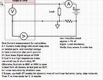
more stuff I have used as a Test Engineer since the mid 70's
Screen shot 2012-05-27 at 8.08.35 PM.PNG
 

Status
Not open for further replies.

Part and Inventory Search

Welcome to EDABoard.com

Sponsor

Back
Top