Continue to Site

Welcome to EDAboard.com

Welcome to our site! EDAboard.com is an international Electronics Discussion Forum focused on EDA software, circuits, schematics, books, theory, papers, asic, pld, 8051, DSP, Network, RF, Analog Design, PCB, Service Manuals... and a whole lot more! To participate you need to register. Registration is free. Click here to register now.

Confused about how to calculate effective power/voltage/current of a pulse wave

Status
Not open for further replies.
RMS gives the equivalent to the integral over the time period when each digital reading is squared, then root of the Sum so it is said that RMS of AC+DC= equivalent True DC power.

more stuff I have used as a Test Engineer since the mid 70's
View attachment 74973
 

"RMS voltage" and "RMS current" make sense.
I've always considered "RMS power" to be a bastardized term that somehow crept into the audio industry. In that context "maximum RMS output power" is generally understood as "maximum output power when the output voltage is a sine wave".
 

SunnySkyguy,

RMS gives the equivalent to the integral over the time period when each digital reading is squared, then root of the Sum ...

To what "digital reading" are you referring? Voltage or current? If so, you have to find the mean of the square before you find the root. Anyhow, what does RMS of power mean?

Ratch
 

"RMS voltage" and "RMS current" make sense.
I've always considered "RMS power" to be a bastardized term that somehow crept into the audio industry. In that context "maximum RMS output power" is generally understood as "maximum output power when the output voltage is a sine wave".
Yes. There has been already a debate about the term RMS power up in this thread.

RMS is a calculation method https://en.wikipedia.org/wiki/Root_mean_square
Normally it makes no technical sense to apply it to power quantities that represent squared magnitude. Why should it be squared a second time.

RMS has also the meaning of a standard deviation in statistical analysis. As mtwieg mentioned, it may be meaningful in some situations to calculate statistical parameters of a power quantity. I think we can agree that the present discussion is not about statistical calculations.

Although the term RMS power has been newly discovered as object of dispute, it seems to me that we achived more clarity regarding the root of the matter, measuring the power consumption of a pulsed load. I would prefer to hammer it out rather then get lost in side issues.
 

²https://en.wikipedia.org/wiki/Watt_RMS
RMS is statistically valid and generally used for low frequencies.
Notice there is some disagreement with some use of the word RMS POWER, as opposed to simply Power using the RMS method.

In general in Engineering, I believe we choose to state our assumptions 1st and then describe the Power in context whether it is Real and Imaginary Power for complex loads, and Peak Power for non-linear considerations, or output Power as in S22 S-parameters where if using dBm or dBi or isotropic antenna standard power, it is always relative to a known standard.

Again RMS Power here uses digital True Power meters using true RMS readings for voltage or current accurate to 5 digits but ONLY accurate for < 500Hz. But you must read and understand the meter's User Manual to ensure you understand the fine print. ... which requires you to read. It's amazing how much you learn from the experts who designed the instrument.. when you read... hint hint

The Wiki link above is about Audio Power where they say

, "(See more in the section Standards at the end of this article). The erroneous term "watts RMS" is actually used in CE regulations."

Yet later quote that,
On May 3, 1974, the Amplifier Rule CFR 16 Part 432 was instated by the Federal Trade Commission (FTC) requiring audio power and distortion ratings for home entertainment equipment to be measured in a defined manner with power stated in RMS terms. This rule was amended in 1998 to cover self-powered speakers such as are commonly used with personal computers

So semantics and historical methods often confuse people to think why do we use RMS method for measuring power.

As a simple example remember P= V²/R , so we know the square law of voltage is used to give power. But we must remember this only applies if R is contant with V(t).

Ideally a real-time multiplier of V(t) & I(t) is best when using RMS method such that orthogonal values are factored rather than independant time measurements of V(t) then I(t) (e.g. imaginary or stored power ) If you know you can prove there is little stored power, it may be OK. I use the X-Y scope of V cs I to show stored power at any frequency of interest from DC to sine or square pulse and use persistence of digital storage to examine this assumption. ** It may interest those who follow Perpetual Motion Machines to know that this is the significant reason why their measurements are INVALID.. because the resonant stored enery of V and I are independantly measured rather than multiplied as vector complex values with stored energy. Hence every example I have seen uses invalid measurement methods!!

Getting the power averaged over a time interval is hard to mathematically for nonlinear transients so "analog integration" circuits are commonly used in simple DVM's is used and then digitized and then those successive values averaged, whereby reducing the noise deviation by 1/√N samples and giving more digits of significant figures. There are some analog challenges in the integrate and dump that introduce error when 5 digits of accuracy are required due to transient memory or nonlinear feed-thu effects of the capacitor circuit, so digital methods of RMS are preferred by those who need it for big AC power systems and want 5 digits to detect small changes.

But as we see, RMS true power must be limited to those who know how to use it.
SO for now, listen to your Prof. and when in doubt Read The Fine Manual (RTFM)
 
Last edited:

SunnySkyguy,

Back in post #9 of this thread, I calculated the RMS value of the voltage from the O'scope graph, and it agreed pretty good with what the scope indicated. But the average value was way off. Could not the scope find the height and width of the pulse for the average value, too?

Ratch
 

Photo says :
Ch 1 Avg. . . = . . 80 . mV
Ch 1 Period . . = . . 8.77 µs
Ch 1 Amplitude = . 2.88 V

. f = 114.0000 kHz . . ( 1/f = 8.77192982 µs )
. V = 3.00 V . . . . . . ( delta V = 120 mv drop from shunt to get 2.88?)
duty = 10.0 % . . . . . . ( Tpw = 0.877192982 µs )

confirm f*Tpw= 114 e3 * 8.77193 e-6 = 1.0000 cycle rounded off
Since not shown in photo, I suspect 10% is correct not 1/12th.

So Vavg should equal 2.88 x 0.100 = 288 mV and not 80mV.

I would check calibration of that scope with signal generator using 0 to 100% duty cycle and compare with DC and keep in mind only 3 sig figs and accuracy of meter specs for each range.

Hey I paid $3000 for my digital scope... this one is only $250.. But then we had calculators in the 70's worth $500. I had two HP9825 desktop calculators each worth $4K alone with 128 digits.

The key is if your result does not make sense.. Calibrate it with a known DC value then slowly vary the duty cycle and observe changes.

BTW When you go to AC mode, it should also measure ZERO for Average.
 

So Vavg should equal 2.88 x 0.100 = 288 mV and not 80mV.

Yes, there's an obvious offset involved with the measurement, I already mentioned it in a previous post. We can't know from a distance, if it's a generator or oscilloscope error, or if an external source is connected in the measurement setup.

Strictly spoken, we don't even know if the two photos are showing the same signal.

I think, that's no principle problem of average measurement and the reason should be easily detectable with hands on the instruments.
 

yes , even the test points of the measurement , what type of probe 10:1 vs 1:1 probe vs Direct Coaxial and the corresponding Scope settings are not mentioned. But if I had a crystal ball, the arrow indicates 0Vdc on Ch 1 can not visually show a 3% or 108mv Error on 3V. Hands on cal check is essential with the built in calibration test port 1KHz signal is recommended at 50% D if it has one.
 

Only one photo is not showing the same signal (function generator's signal), which is the XBee.
They are connected in the same way, the only thing I changed is the true rms in the red multimeter.


Yes,
All discussion is about which one is correct. No one is touching my question about Fourier transform of the signal.. Theoretically, it should be the correct and best way to calculate the voltage as taking some harmonic to a some accuracy and sum the rms values of the peak.
No one talk about that. ..

It became more complicated in fact .. some posts says rms .. other says avg . .. I am still in the middle ..
I understand the fault measurement of the multimeter, I never trusted them ... But the Oscilloscope should show the correct wave.


This waveform is much much simpler than any output power from an amplifier which is very complex... I didn't have time to make more experiment and play with the width of the pulse and the frequency .. I promise to come back with info and picture more about the case..
I still believe, I might have wrong, the rms measurement of the oscilloscope is the best measurement.

When any analog signal analysis to a digital signal, Digital signal analyses start with assuming a constant pulse signal that is multiplied with f(x). It means that if we take out the pulse (which is a DC voltage) the waveform comes down to the X axis and there will be positive and negative part.
Having positive and negative part, means you can never use average to calculate the voltage.. This is my argument.. I will try to prov that using my instruments. .. I need some time to do so .. Please go a head doing such a test if you have similar instruments.
 

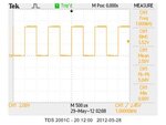
Here is another example. Very simple .. A square wave with 1 Khz (500 micro sec width)

t1= 500 micro sec
T=1000 micro sec

you see the voltage and the calculation ..
What is the effective (equivalent to DC) voltage here? very simple ..

Note: The waveform starts from 0 and has a peak of 5.04 Volt. Prob is at 10X
simple_squarewave.jpg

BTW: Multimeter reads 2.473 volts (I dont trust this reading .. just as a reference)
The multimeter is called TENMA 72-7755

If the square wave replaced with sinusoidal waveform .. what will be the result .. more voltage or less?
 
Last edited:

Note: The waveform starts from 0 and has a peak of 5.04 Volt. Prob is at 10X
BTW: Multimeter reads 2.473 volts (I dont trust this reading .. just as a reference)
Is 5.04 V the generator setting? At first sight, the displayed average of 2.5 V fits the expectable value better than the DMM number. But, did you review the vertical accuracy specification in your oscilloscope manual? According to a typical oscilloscope specification, the real voltage could be 2.45 or 2.55 as well.

Having positive and negative part, means you can never use average to calculate the voltage.
What do you mean with "the voltage" in this regard? A signal has different parameters which can be measured. Each has a specific meaning. If you mean a bipolar square wave, you would most likely measure Vp or Vpp as characteristic quantity.
 

I did mean the measured voltage by the oscilloscope.
I called it VP as it starts from 0.. So the whole siganl is on the positive side.. No negative part is available.

Actually, the signal is coming from the Oscilloscope itself.. When you prob calibrate you use this signal ..

The Oscilliscope is called Tektronix TDS 2001C 50MHZ 500MS/S
 

The probe calibration output is only specified with a typical output voltage of 5V and no exact accuracy or duty cycle specification for most oscilloscopes. All reported results are plausible, it's impossible to determine if the DMM DC measurement involves a systematic error.
 

Status
Not open for further replies.

Part and Inventory Search

Welcome to EDABoard.com

Sponsor

Back
Top