grizedale
Advanced Member level 3
Hello,
We are in Spain and are having big trouble (and angry customers) with a 6.8W flashing LED light which is a warning light…………
The linear regulator (LM350) keeps blowing up (its case is blown wide open).
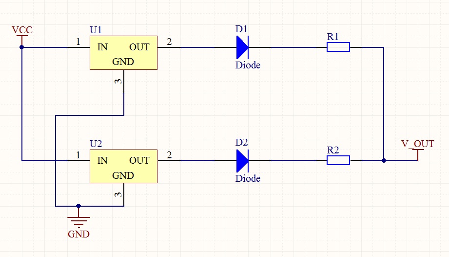
Here is the schematic.
http://i48.tinypic.com/2cfxwqq.jpg
(the schematic uses LT1085 regulator because LTspice doesn’t have a model for LM350)
-also, as you can see, we’ve already put a 3R9, 25W resistor in series with the LM350 to allow the LM350 to run cooler, but LM350 is still blowing up.
WH25 resistor series:
http://www.welwyn-tt.com/pdf/datasheet/wh.pdf
Here is the current in the 0R39 resistor (also same as input current)
http://i49.tinypic.com/35bt3c5.jpg
Here is the voltage on the 100uF output cap (the voltage that drives the LEDs)
http://i46.tinypic.com/5yg4ly.jpg
Here is the voltage at the “IN” terminal of the linear regulator
http://i46.tinypic.com/orj69s.jpg
Also:-
Vin = 28V
Power dissipated in LM350 is 6.2W.
Power dissipated in the 25W input resistor is 11W
The LEDs are Osram platinum dragon (LY W5SN)
LED datasheet:
http://www.thorlabs.com/Thorcat/21700/21732-M01.pdf
The LM350 is attached to a heatsink with an “LR20” insulating (also thermally conductive) spacer made by Denka:
Datasheet of thermally conducting material:
http://www.reipower.it/pdf/REI-Denka.pdf
LM350 Datasheet
http://www.ti.com/lit/ds/symlink/lm350-n.pdf
---------------------------
The LED flash pattern is
ON for 44ms
OFF for 10ms
ON for 44ms
OFF for 10ms
ON for 44ms
OFF for 298ms
…..then repeat endlessly
----------------------------
We originally get a contract company to design this for us but now they’ve disbanded.
The only thermal test data which we can find on this product is a thermal camera image of the PCB, which indicates that the surface of the LM350 was 123 degC.
-Unfortunately it doesn’t show what the ambient temperature was when this image was taken, or whether or not the PCB was enclosed in its enclosure (I suspect it wasn’t in its enclosure, as they wouldnt have been able to take the thermal image if it was)
This product is placed outside in the sunshine, and we wonder if the product’s amber diffusor is acting as a heat-trap, making the internal ambient far hotter than the external ambient temperature?
First of all, the the thing that concerns us is the flashing nature of this product.
…..So the LM350 linear regulator is conducting 3.2A pulses of current with the above flash pattern.
…..this means the “IN” terminal voltage of the LM350 is wildly going up and down as shown above.
….i am wondering if this is a harbinger of instability problems in this linear regulator and maybe linear regulators are just not meant for such pulsating current flow?
There are input and output caps connected up to the LM350 but they are not that physically near to it……..they are each about one-and-a-half inches of PCB track away from the LM350.
The heatsink on which the LM350 is mounted is not that big, and has no fins……its about 1mm thin metal………..the crazy thing is that the base of the product, on which the LM350 PCB + heatsink sits, is a huge aluminium bar and it’s unfortunate that the LM350s weren’t thermally coupled up to that in some way.
(Another point is that the LEDs are in parallel with no series equalising resistors, but we find that’s OK)
Anyway, I wonder if you believe that this ON/OFF operation of a linear regulator is a bad idea? (i.e. with pulsating 3.2A current)
We are in Spain and are having big trouble (and angry customers) with a 6.8W flashing LED light which is a warning light…………
The linear regulator (LM350) keeps blowing up (its case is blown wide open).
Here is the schematic.
http://i48.tinypic.com/2cfxwqq.jpg
(the schematic uses LT1085 regulator because LTspice doesn’t have a model for LM350)
-also, as you can see, we’ve already put a 3R9, 25W resistor in series with the LM350 to allow the LM350 to run cooler, but LM350 is still blowing up.
WH25 resistor series:
http://www.welwyn-tt.com/pdf/datasheet/wh.pdf
Here is the current in the 0R39 resistor (also same as input current)
http://i49.tinypic.com/35bt3c5.jpg
Here is the voltage on the 100uF output cap (the voltage that drives the LEDs)
http://i46.tinypic.com/5yg4ly.jpg
Here is the voltage at the “IN” terminal of the linear regulator
http://i46.tinypic.com/orj69s.jpg
Also:-
Vin = 28V
Power dissipated in LM350 is 6.2W.
Power dissipated in the 25W input resistor is 11W
The LEDs are Osram platinum dragon (LY W5SN)
LED datasheet:
http://www.thorlabs.com/Thorcat/21700/21732-M01.pdf
The LM350 is attached to a heatsink with an “LR20” insulating (also thermally conductive) spacer made by Denka:
Datasheet of thermally conducting material:
http://www.reipower.it/pdf/REI-Denka.pdf
LM350 Datasheet
http://www.ti.com/lit/ds/symlink/lm350-n.pdf
---------------------------
The LED flash pattern is
ON for 44ms
OFF for 10ms
ON for 44ms
OFF for 10ms
ON for 44ms
OFF for 298ms
…..then repeat endlessly
----------------------------
We originally get a contract company to design this for us but now they’ve disbanded.
The only thermal test data which we can find on this product is a thermal camera image of the PCB, which indicates that the surface of the LM350 was 123 degC.
-Unfortunately it doesn’t show what the ambient temperature was when this image was taken, or whether or not the PCB was enclosed in its enclosure (I suspect it wasn’t in its enclosure, as they wouldnt have been able to take the thermal image if it was)
This product is placed outside in the sunshine, and we wonder if the product’s amber diffusor is acting as a heat-trap, making the internal ambient far hotter than the external ambient temperature?
First of all, the the thing that concerns us is the flashing nature of this product.
…..So the LM350 linear regulator is conducting 3.2A pulses of current with the above flash pattern.
…..this means the “IN” terminal voltage of the LM350 is wildly going up and down as shown above.
….i am wondering if this is a harbinger of instability problems in this linear regulator and maybe linear regulators are just not meant for such pulsating current flow?
There are input and output caps connected up to the LM350 but they are not that physically near to it……..they are each about one-and-a-half inches of PCB track away from the LM350.
The heatsink on which the LM350 is mounted is not that big, and has no fins……its about 1mm thin metal………..the crazy thing is that the base of the product, on which the LM350 PCB + heatsink sits, is a huge aluminium bar and it’s unfortunate that the LM350s weren’t thermally coupled up to that in some way.
(Another point is that the LEDs are in parallel with no series equalising resistors, but we find that’s OK)
Anyway, I wonder if you believe that this ON/OFF operation of a linear regulator is a bad idea? (i.e. with pulsating 3.2A current)