Continue to Site

Welcome to EDAboard.com

Welcome to our site! EDAboard.com is an international Electronics Discussion Forum focused on EDA software, circuits, schematics, books, theory, papers, asic, pld, 8051, DSP, Network, RF, Analog Design, PCB, Service Manuals... and a whole lot more! To participate you need to register. Registration is free. Click here to register now.

Help to drop voltage !

Status
Not open for further replies.

thebadtall

Full Member level 6
Joined
May 17, 2012
Messages
339
Helped
12
Reputation
24
Reaction score
12
Trophy points
1,308
Location
Hellas
Activity points
3,605
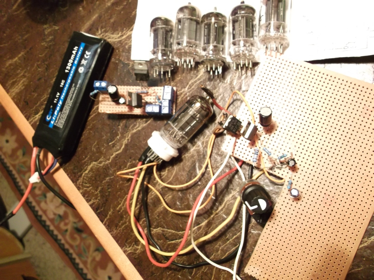
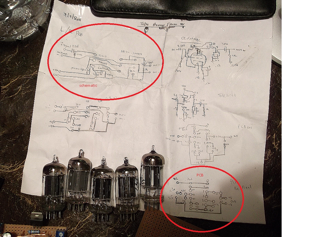
Hello, ive been working on a 12v battery preamp 12au7 tube project, wich ended quite good.

Now I have found a new project to work on, wich needs 300v dc to feed the 12au7 plate.

I dont have the transformer, but I thought I could use a fluorescence tube transformer wich is 430v AC.
The problem here is that I dont know how to reduce the voltage to 300v. Can I use zenner or they will blow ?

Any suggestions please ?Thank you.
 

Dear thebadtall
Hi
What is the main voltage that you want to decrease it ? 430 volts ? if yes , it depends on how much current do you need . if it is low , a zener diode and a series resistor can be a good idea .
Best Wishes
Goldsmith
 

the transformer is 220v to 430v around 70watt
The P max of the 12au7 tube is less than 5watt
Only one zenner can do the job , or should I put zenner in series ?

I have Tested it in a simulator and it doesnt drop to less than 350v
 

An easy way to get the voltages you want is to use two 12V mains transformers back-to-back. The first steps the mains (230V) down to 12V, and the second steps the 12V back up to 230V.

When you rectify the 230V RMS, you should get a little over 300V DC. The extra voltage can be dropped with an RC supply smoothing network, which you probably wanted anyway.

As an added bonus, you can use the 12V from the midpoint of the transformers for the heaters.

[OT]
OK, I'm curious. In your previous circuit, were you running the 12AU7 with only 12V (or less) on the plate? That's extremely unusual.
[/OT]

edit: Dropping the extra voltage with a Zener is a bad idea as it doesn't reduce ripple. It's better to drop it with a resistor, followed by a capacitor to ground. Even better would be a voltage regulator.
 
Last edited:

Hi again
If you want 5 watt , you have to use some zener diodes in parallel . or higher wattage zeners ( those are a bit expensive , hence you'd better to use some of them in parallel ).
Good luck
Goldsmith
 
...I thought I could use a fluorescence tube transformer wich is 430v AC.
Is that 430V RMS? If so, you will get about 600V DC after rectification. That is very high, double what you need.
 

Hello again, thank you for help !

1st
An easy way to get the voltages you want is to use two 12V mains transformers back-to-back. The first steps the mains (230V) down to 12V, and the second steps the 12V back up to 230V.

Can you explain a bit further on how I will connect those transformers ? Those are typical 220v to 12v ?

2nd
OK, I'm curious. In your previous circuit, were you running the 12AU7 with only 12V (or less) on the plate? That's extremely unusual.

The preamp played very nice and warm, with very low gain though, power by a 12v LiPo battery (from some R/C projects ive done before)
I used a regulator also to increase gain ( IRF510 and LM317 ) (if im not wrong)

I can upload some pics if you want.

Is that 430V RMS? If so, you will get about 600V DC after rectification. That is very high, double what you need.
3rd The transformer is 430Vac rms yes
 
Last edited:

Can you explain a bit further on how I will connect those transformers ? Those are typical 220v to 12v ?
Yes, just ordinary mains transformers, connected like in the pic below.

The preamp played very nice and warm.....
I can upload some pics if you want.
Thanks, a pic and a circuit diagram would be nice.

---------- Post added at 13:01 ---------- Previous post was at 12:59 ----------

 
Here is it


and the schematic
m8zat3.jpg


About the back to back transformer.. thanks, I understood !
 
Last edited:

Wow, interesting!
If you're interested in valve audio equipment, you may like to join https://www.diyaudio.com/. It's a nice forum with a lot of enthusiastic and knowledgeable people, and an active tube section.
 

Dear godfreyl
Hi
I was wondering that are these tubes still available ? ( i know for some applications such as RF systems still they are available .) are those , available , really ?
Thank you
Goldsmith
 

Hi Goldsmith

Yes! Some common types are easily available even here in South Africa. In countries like USA many more types are available. They are not only used by hobbyists; Some guitar amplifiers and expensive hifi equipment still use them too.

Regards - Godfrey
 
though available, tubes are expensive. ive bought mine in ebay ( used )as a 10 tube lot quite cheap. however the half tubes were depleted, but the other half do the job great!
 
Dear godfreyl
Thank you very much for your clarifying . i thought , they are not available , and now i'm sure that they are available . but how can i learn about them , for example i know , how to design an amplifier with transistors , as well . but how can i learn how to design with tubes ?
Thanks and Best Regards
Goldsmith

---------- Post added at 19:53 ---------- Previous post was at 19:52 ----------

And Dear thebadtall
Thank you for your clarifying too .
Best Regards
Goldsmith
 

I believe Morgan Jones' books "Valve Amplifiers" and "Building Valve Amplifiers" are very good. I don't have either, but have often heard them recommended and praised.
 
personally I design tube amps according to the tube datasheet, having in mind that I'm making a Class A amp
:D
 
Thank you for your good suggestions . by the way , i hear that when EMP ( Electro magnetic pulse ) used , tubes still can work without problem . is that correct ? if yes , why ?
Thank you very much
Respectfully
Goldsmith
 
i hear that when EMP ( Electro magnetic pulse ) used , tubes still can work without problem . is that correct ? if yes , why ?
Thank you very much
Respectfully
Goldsmith

Electromagnetic pulse, in theory, shorts-circuit the silica of transistor,semiconductors etc.
Since tubes are Not made from silica but from metal - alloys etc - they are immune to EMP.
If the circuit does not contain transistors it will survive. However, nowdays everything has at least 1 transistor.
For instance all power supplies are switching, whereas old power supplies are just a heavy transformer..
Old circuits will survive !

(at the moment im assembling a tube transistorless circuit !!)
 
Dear thebadtall
Thank you very much for your description . but how a silica junction will destroy with a powerful magnetic flux ?
Best Regards
Goldsmith
 
During a nuclear explosion - E.M.P. high voltages occur, If I remember correct, the electrons that travel have an average amperage in the stratosphere of about 50 amperes per square metre, wich move to the gravity center (earth ground) , and short cirtcuiting whatever find in their way.

So, a good solid valve circuit will survive (it will survive because the PCB will be 20x20cm , so if 1sqm = 50A, 20sqcm will be less than 1/4 so around 13A. Now, 13A for the smallest part of that circuit will be very much, but dont forget the great tolerance old circuits used to have ! sometimes >20% )


whereas a laptop will fry and melt ! (LOL ! Imagine 10A through the cpu !)
 
Status
Not open for further replies.

Similar threads

Part and Inventory Search

Welcome to EDABoard.com

Sponsor

Back
Top