godfreyl
Advanced Member level 5
The inductor is much too big. If you connect a load (even a light bulb) to the output, the voltage will drop and the current will be very low. I think L should be about 100 times smaller.the full cycle period is 50HZ...
L=8.8H
Cut off frequency should be much higher than 50Hz. If the PWM frequency is 5KHz, then the cut off frequency could be about 500Hz.Cut off frequency..F_(cutoff frequency)=1/(2π √LC)...........
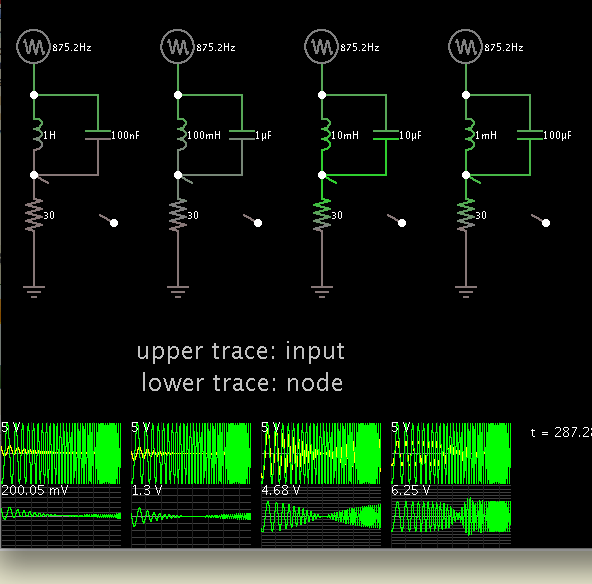
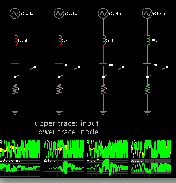
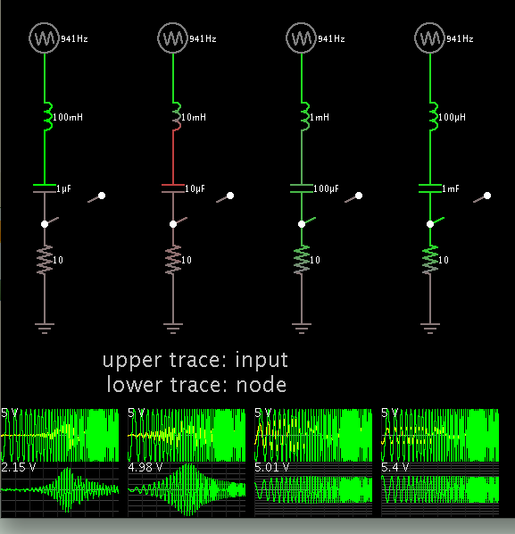
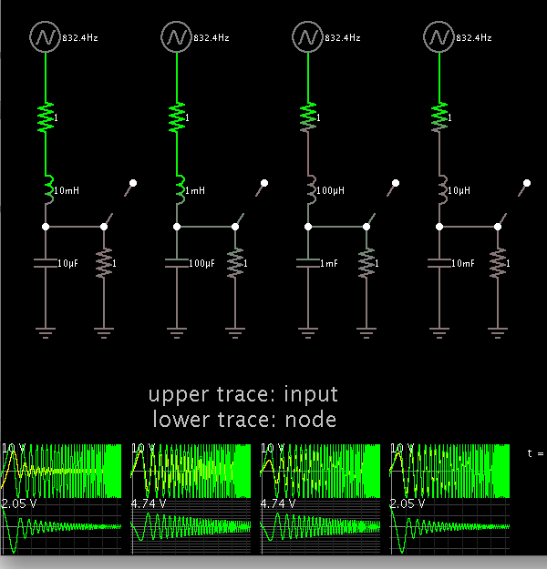
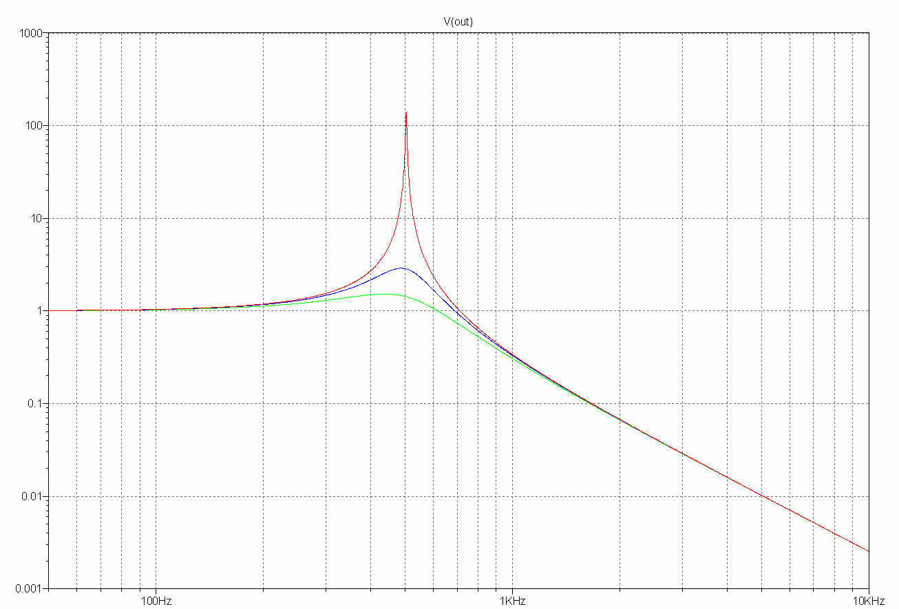
L=100mH, C=1uF may be good values. The inductor can also be smaller. If you choose L=10mH, then C=10uF.