Continue to Site

Welcome to EDAboard.com

Welcome to our site! EDAboard.com is an international Electronics Discussion Forum focused on EDA software, circuits, schematics, books, theory, papers, asic, pld, 8051, DSP, Network, RF, Analog Design, PCB, Service Manuals... and a whole lot more! To participate you need to register. Registration is free. Click here to register now.

Help me out with turning off n-MOSFET (Si9926)

Status
Not open for further replies.

nramesh

Junior Member level 1
Joined
Jun 27, 2006
Messages
15
Helped
0
Reputation
0
Reaction score
0
Trophy points
1,281
Activity points
1,460
Hi i need your support in solving the following issue.

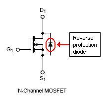
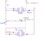
I'm facing issues in turning off n-MoSFET (Si9926)..circuit is attached.. can you please suggest me, what is wrong with this circuit? It is not turning off si9926.. even 5v is present at gate of si9926, it is not getting turned off.. any other changes required?

Best regards,
Ramesh
 

Attachments

  • AutoSwitching.png
    AutoSwitching.png
    13.5 KB · Views: 91

Re: Turning off n-MOSFET

With an N channel MOSFET:
A) The drain must be at a higher voltage (i.e. more positive) than the source.
B) To switch it on, the gate must also be more positive than the source.

I don't understand how your circuit is supposed to work.

The drains of Q1 are connected to the anode of a diode, so they will never conduct any current. Q3 is connected as a source follower, so if there is a positive voltage on VAC_AdapterDC, then there will be a smaller positive voltage at TP14, but there is nothing to pull that voltage down. Q2 might conduct current from VCC to VAC_AdapterDC, depending on the voltage at TP13.

Maybe you want to supply current to VCC from either VBATTERY or VAC_AdapterDC. If so, you should be using P channel MOSFETs.
 

Re: Turning off n-MOSFET

ok p channel needs neg pulse or neg voltage on gate with respect to source to go on... if the drain is neg the gave is neg=on
and your drawing is wrong regarding the fet connection see data sheet
New Bitmap Image.JPG
 
  • Like
Reactions: js

    js

    Points: 2
    Helpful Answer Positive Rating
Re: Turning off n-MOSFET

Dear godfreyl ,
Thanks for quick reply.
Yes;I want to supply current to Vcc either from Vbattery or Vac.. so n-channel MOSFET should not be used for this application? In one of the vendor application note, they recommended n-Channel MOSFET for this type of battery charger application.. anyway i will go back to check about device selection itself..
This Si9926 supports logic control (can be driven using GPIO)... (referred their selection guide;). I guess it supposed to work with simple connection to either vcc(>2.5V) or gnd for controlling it...
if gate of n-channel MOSFET(Q1/Q2) is grounded, MOSFET will turn on,isn't it?
or i am missing something fundamentally?
Best regards,
Ramesh
 
Last edited:

Re: Turning off n-MOSFET

I couldn't find info about the Si9926. From your drawing, I assumed it is just two MOSFETs on a chip. Is that wrong? Can you post a link to a datasheet?
 

Re: Turning off n-MOSFET

Dear godfreyl,
Thanks for your time...
Si9926 product page and data sheet link ----
https://www.vishay.com/mosfets/list/product-68606/
www.vishay.com/docs/71633/71633.pdf

i will rephrase the issue, if to be more clear on what is the issue ...

vbat - 6.3V
Vac - 5.73V
issue:2.5v / 3.3v / 5v / gnd - any voltage @ gate of Q1 --- Q1 is always ON (i.e current is supplied to vcc from "battery(vbat)") ; please ignore Q2/Q3 in the image..
 

Re: Turning off n-MOSFET

vbat - 6.3V
Vac - 5.73V
issue:2.5v / 3.3v / 5v / gnd - any voltage @ gate of Q1 --- Q1 is always ON (i.e current is supplied to vcc from "battery(vbat)")
The source is connected to vbat i.e. +6.3V
The gate is between gnd and +5V
Therefore the gate is always negative compared to the source.
Therefore the MOSFET is always switched off.

But the MOSFET has a reverse protection diode and the MOSFET is connected upside-down, with the drain more negative than the source, so current is flowing through the protection diode.

Have another look at the explanation (at the top of post 2) of how to connect an N channel MOSFET.

If you swap the source and drain connections, you will be able to switch it on and off, but the output voltage will not be very high when it is on.

If you want the output voltage to be close to Vbat when it is switched on, you must use a P channel MOSFET.


Re: Turning off n-MOSFET

Hello godfreyl
do u understand what does he want to do ?
i understand he wants to gate q2 that will further gate q3 and then what ?
next he wants to gate q1 and to do so the diode should be inverted and vcc should be positive or zero volktage and then what ?
https://www.electronics-tutorials.ws/transistor/tran_7.html
 
Last edited:

Re: Turning off n-MOSFET

Dear godfreyl, dselec,
Thanks for your response..
I guess i understand whare i made mistake.. I have attached modified circuit..

This circuit is intended to work as following..
Source 1 - Vbat from SLA battery 6.3V
Source 2 - From AC-DC converter 5.73V

When Source 2 is present, Vcc is from source 2; Q1 will in OFF
When Source 2 is removed, Vcc is from Source 1; Q1 will be ON;
Is this modified circuit correct? do you recommend any other circuit?

Thank you very much for valuable review points.i am learning more every minute...
image:https://obrazki.elektroda.pl/65_1335896662.png
 

Attachments

  • AutoSwitching-2.png
    AutoSwitching-2.png
    16.8 KB · Views: 72

Re: Turning off n-MOSFET

Hi,

Just curious, what could be the disadvantage for you if you use just two diodes going to Vcc?
In this very simple configuration, Vcc will get its current from the diode that has a higher voltage at its anode.

Kerim

Added:
I guess you cannot use this simple solution since you have an AC to DC supply with the relatively low voltage (5.73V) only.
 
Last edited:

Re: Turning off n-MOSFET

ok now lets see you start from vbatt go thru d2 to s2 then u go to s1 and (do not pas thru fet cause + cant pass thru source) but it will go thru the diode on s1 thru d1 to vcc , more we havev to check out if there will be some current going to q2 d1 and then q2 s1.
now if vac adaptor is working q1 g1 g2 has zero that will make sure that q1 will not work and if adaptor not working then there is positive gate for q1 and alls good.
תמונה .JPG
 

Re: Turning off n-MOSFET

I guess i understand whare i made mistake.. I have attached modified circuit..
It is better, but still bad. Now, in Q1, the current goes through two MOSFETs. One is the right way around, but the other is upside down. See pics below.

There is one more problem in your circuit:
If the voltage from the AC adapter is 0V, the battery is switched on.
If the voltage from the AC adapter is 5.7V, the battery is switched off.
This is good.

If the voltage from the AC adapter is 3V, the battery is switched off.
If the voltage from the AC adapter is 2V, the battery is switched off.
Is this OK?
bad.GIF
 

Re: Turning off n-MOSFET

On post #1, ZXM61P03F is actually a P-channel MOSFET but drawn as N-channel.
 
Last edited:

Re: Turning off n-MOSFET

u can modify the circuit to look somthing like that with only 1 set of fet or even without fets at all.
all u want is vac out to vcc and when no vac then batt out right ?
modified.JPG
 
Last edited:

Status
Not open for further replies.

Similar threads

Part and Inventory Search

Welcome to EDABoard.com

Sponsor

Back
Top