Welcome to our site! EDAboard.com is an international Electronics Discussion Forum focused on EDA software, circuits, schematics, books, theory, papers, asic, pld, 8051, DSP, Network, RF, Analog Design, PCB, Service Manuals... and a whole lot more! To participate you need to register. Registration is free. Click here to register now.
Often a parallel combination R & C is used between Chassis and Circuit ground. What is the purpose of the resistor. Resistor used is of 1 MOhms normally. I want to know what will be the effect if I increase the resistor value to 10 MOhms ?
Re: Purpose of parallel combination R & C is used between Chassis and Circuit ground
It's there to leak away any charge that has built up between chassis and real ground without allowing enough conduction that it could pass lethal current. The capacitor is to offer lower impedance to high frequencies. Usually you see this circuit between primary and secondary sides of switch mode PSUs. The resistor value isn't critical, if you make it too low the current might reach danger level and if you make it too high it may not conduct leakage away sufficiently. 10M is probably a risky value, I would suggest you use 4M7 or lower. Note the voltage rating of the capacitor, the resistor should also be rated for high voltage, most small axial resistors are only rated to 250V,
Re: Purpose of parallel combination R & C is used between Chassis and Circuit ground
Hi Brian, thanks for the reply. This circuit I have seen is in an analog module. The maximum input voltage from field is 30VDC. Does that voltage plays any role in determining the value of the resistor or it purely for safety purpose ? No way I can remove the resistor and keep it open with only the capacitor installed ?
Re: Purpose of parallel combination R & C is used between Chassis and Circuit ground
It's purely for safety purposes, I would say the manufacturer perceives a risk of voltage building up and wanted it discharged safely. It may be that you have an isolating power transformer in the circuit somewhere. Although such a transformer doesn't allow direct conduction between primary and secondary sides, there will still be a degree of capacitive coupling which can elevate the isolated side to a potential above ground. That resistor is there to safely leak it away. Don't rely on the capacitor alone, in fact without the resistor there is a risk of the capacitor breaking down.
Re: Purpose of parallel combination R & C is used between Chassis and Circuit ground
The circuit is powered up by 24V with ground referenced as 0V_F_D.
24V is then converted to 15V and ground referenced as 0V_F_A. 24V is isolated from 15V using a push-pull transformer.
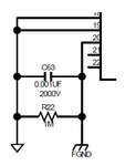
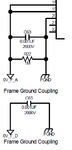
In between 0V_F_D & FGND, we have only the capacitor (please see attachment) and between 0V_F_A and FGND, we resistor and capacitor.
We have to perform an insulation resistance test from 24vdc input to FGND. The passing level is >10Mohm before a damp heat test and > 1Mohm after the test. Do you think we should be able to pass the test succesfully with the above arrangement (assume the layout is perfect) ? I think we should be able to pass the test since the insulation test is applied between 24V and its respective ground (i.e. 0V_F_D) and 0V_F_D to connected to FGND through a high voltage capacitor with no resistor in parallel. Your opinion please.
Re: Purpose of parallel combination R & C is used between Chassis and Circuit ground
I think it should be OK. If I follow what you are explaining, the resistor isn't across the two points where you are applying the insulation test voltage. The easiest way to confirm this is with a simple Ohm meter, just connect across the test points and see if you measure 1M or not. It might take a few seconds for the reading to settle as you might have to leave time for the capacitors to charge up.
This site uses cookies to help personalise content, tailor your experience and to keep you logged in if you register.
By continuing to use this site, you are consenting to our use of cookies.