Continue to Site

Welcome to EDAboard.com

Welcome to our site! EDAboard.com is an international Electronics Discussion Forum focused on EDA software, circuits, schematics, books, theory, papers, asic, pld, 8051, DSP, Network, RF, Analog Design, PCB, Service Manuals... and a whole lot more! To participate you need to register. Registration is free. Click here to register now.

solar current and voltage measurment at same time+range is 0-5amp & 0-20 v

Status
Not open for further replies.

nikhiljoshi

Newbie level 4
Joined
Apr 10, 2012
Messages
5
Helped
0
Reputation
0
Reaction score
0
Trophy points
1,281
Activity points
1,319
Dear sir,

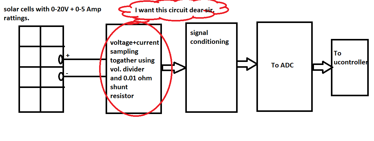
1) is it possible that we measure the current(range 0-5amp) and voltage(0-20v) at same time coming from solar channel ?

if possible then please explain me what is the combine circuit for above configuration ?
I want the outputs as below which are compatible to my ADC channel :
-0-5 amp should be convert to 0-0.5 volt.
-0-20 volt should be convert to 0-5 volt.
2)I am using 0.1 ohm/5 watt resistor for 0-5 amp current.but it is highly heated in almost 5 minutes.Is it normal sir?
 

1.
If the data acquisition devices have one A/D converter, that need to be multiplexed to the two channels. In other words, each input channel will be sampled sequentially . Therefore, if you use two channels, those channels cannot be sampled simultaneously and a time gap exists between consecutive sampled channels. This time gap is called the channel skew. You can think of the channel skew as the time it takes the analog input subsystem to sample a single channel. In practice, the sampling rate depends on several characteristics of the analog input subsystem including the settling time and the gain, as well as the channel skew. If you cannot tolerate channel skew in your application, you must use hardware that allows simultaneous sampling of all channels.

2.
That’s a normal situation at 5 Amps on a 0.1 shunt resistor, as the peak power P = RI2 = ~ 2.5W.
You need to lower this value of the shunt resistor to 0.01 ohms in order to minimize dissipated power up to 0.25W. But as the voltage drop across the shunt is proportional to the current flowing through it and since its resistance diminish we need to compensate using an additional amplifier circuit. (Amplifier gain= 10)
 
Thank u sir for replying...i am using two different ADC channels..;but my problem is that,what is the combine circuit( voltage divider which measures above voltage range+shunt resistor 0.01 ohms for above current range). And one another thing is that this ratings are coming from the single solar panel and I have to measure this together sir..I know that how to amplify them and the whole ADC portion..but don't know that can we measure this current and voltage from the single channel to gather at same time ???

I'm attaching solar.png which would help you to understand my problem...
 

Status
Not open for further replies.

Part and Inventory Search

Welcome to EDABoard.com

Sponsor

Back
Top