Continue to Site

Welcome to EDAboard.com

Welcome to our site! EDAboard.com is an international Electronics Discussion Forum focused on EDA software, circuits, schematics, books, theory, papers, asic, pld, 8051, DSP, Network, RF, Analog Design, PCB, Service Manuals... and a whole lot more! To participate you need to register. Registration is free. Click here to register now.

Diodes in SP Bridge serving as Flywheel Diodes

Status
Not open for further replies.

jonnybgood

Full Member level 4
Joined
Dec 28, 2010
Messages
214
Helped
3
Reputation
6
Reaction score
1
Trophy points
1,298
Activity points
3,011
I am simulating a single Phase Full Wave Uncontrolled Rectifier without a flywheel diode. From the waveforms I found that the Inductive Load voltage is not going into negative part due to inductor current.

Is it that the other two diodes in the bridge are serving as two flywheel diodes in series for dissipating the inductor current? If yes, why is that I read some online sources describing negative load voltages without the flywheel diode connected? I am using PLECS with matlab. With the half wave rectifier I have managed to demonstrate this phenomena since there is only one diode.
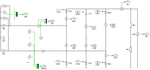
 

theoretically you are right, the voltage (from + output of 4 diode bridge to - output of diode bridge) can be negative some volts only (that is the voltage drop across two diodes). It can only do that during the zero crossing of the AC input voltage. So considering mains voltage rectification, it can't go negative (from a practical standpoint of view).

The only reason that I can think of, is to avoid reverse recovery issues with the 4 bridge diodes. If at a zero crossing all 4 diodes conduct due to the inductor current, you may get a voltage/current spike during diode turn on. By adding a seperate freewheel diode, all 4 bridge diodes will not be on at the same time.
 
Thanks a lot. Regarding the issue of the spike you mention(without flywheel): would this reduce the efficiency of the system and also induce a lot of unwanted harmonics which will have adverse effects sometimes?
 

Correct, current/voltage spikes reduce efficiency (somewhat), and they will generate EMI issues.

Is this just for learning, or for a real world high power application?
 
To tell you the truth, it is for an assignment where I have to simulate the circuits and explain what is happening. Have you ever worked with matlab and PLECS?
 

I have no experience with PLECS and I don't even know what it is is.

Do you also need to explore the non-idealities in rectifiers, inductors and capacitors? You may check whether the models you use do behave more or less as real diodes. Diode reverse recovery, and forward recovery may show results that cannot be explained based on ideal components.
 
No, actually I am asked to work with ideal components, no forward voltage, ideal inductors, etc.. I am trying to simulate 3 Phase FW cont. rectifier and I got the following waveworm(attached). I have an inductive load 0.002Henries and 1 Ohm. What do you think? What is the difference between double pulse and single pulse for firing thyristors and when are they used? Why is it that the load voltage is rectified sine wave not like sawthooth?

3pFW waveform.png
 

Attachments

  • 3pFW block..pdf
    8.5 KB · Views: 65
  • 3pFW schem.png
    3pFW schem.png
    83.3 KB · Views: 54

Hello,

The thyristor thing I don't know at this moment.

Rectifier waveform
If there was a capacitor across the bridge, you would get the decay similar to a full wave rectifier in a regular power supply, but you have an inductor here. The load current is so large that the inductor impedes rappid current changes. Therefore the rectifier output current doesn't become zero. To enable this, at least two diodes must conduct (or thyristors) to form a closed path.

The top diode connected to the leg with the momentary highest voltage and the bottom diode connected to the leg with the lowest momentary voltage do conduct and dictate the output voltage across the rectifier.

Your rectifier as shown in the graphs operate in so-called continuous (current) mode.
 
This is more like it :) .. What do you think. I changed the firing source to a one directly synchronized the each phase. There is one with 2milli Henry and thyristor currents are not so filtered out. However with 20milli Henry the thyristor current is more filtered.

3pFW waveform.png
3pFW waveform 20milliHenry.png
 

What is your design goal?

If it is the lowest ripple, you may add a capacitor across the resistor to divert harmonic currents to the capacitor. Do not add a capacitor across the bridge.

As you can see from the graphs, using a large series inductor delays the response to the pulses. In addition, you get a voltage spike across your load when the load current changes rapidly.

There seems something strange in your graphs. The load current looks smooth, but the load voltage (voltage across resistor?) is not, this should not happen with a resistive load.
 
No actually the Vload voltage is measured across the resistor and inductor in series not across resistor only.. does this make sense?
 

Status
Not open for further replies.

Similar threads

Part and Inventory Search

Welcome to EDABoard.com

Sponsor

Back
Top