Continue to Site

Welcome to EDAboard.com

Welcome to our site! EDAboard.com is an international Electronics Discussion Forum focused on EDA software, circuits, schematics, books, theory, papers, asic, pld, 8051, DSP, Network, RF, Analog Design, PCB, Service Manuals... and a whole lot more! To participate you need to register. Registration is free. Click here to register now.

Inductor of LC tank oscillator:single ended/differential

Status
Not open for further replies.

palmeiras

Full Member level 6
Joined
Feb 22, 2010
Messages
375
Helped
61
Reputation
122
Reaction score
50
Trophy points
1,308
Location
South America
Activity points
4,199
Hello guys,

Is there any electrical difference between the center tapped inductor and the normal one?
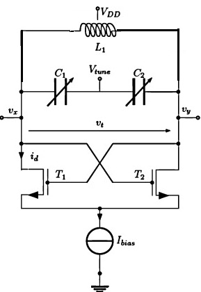
I know that the differential one is usually using in design of oscillators, for instance, in the figure attached. Neglecting the area, what is the electrical difference between these two devices? Is there any?

Thanks in advance,

59_1333839095.jpg
 

The tapped inductor has two (or more) windings overlapping. Each winding affects the other.

Schematic diagrams don't always show this concept.

It is possible to construct a tapped inductor so the windings don't affect each other. However this does not really fit under the term 'tapped inductor'.

So there's the question, can two independent coils do the job of a tapped inductor?

To my understanding, no. The inductors (the windings, that is) need to be close enough together that the flux fields can interact.

As for the converse question: Can a tapped inductor be usable as a normal inductor? There is more than one way to connect it. I think it depends on what waveform you apply, however it is connected. If you apply transients then you will tend to get interaction between the windings. If you apply slow smooth sinewaves then the windings will not react as they do to transients.
 
Hello BreatheRad,
Thank you very much for your reply. You told about the interaction between the winding (the eletrogramanet effects). What is the result of this interaction?
For instance, considering two inductors with L=0.5 n in series, resulting in Ltotal = 1n H. Now comparing with a center tapped inductor with L = 1n.
Which parameters of these inductors would be different? Quality of factor? Self-resonance frequency? As you told about interaction between the inductors, I would think about mutual inductance.. But I cannot see the final results. What is it?
 

You told about the interaction between the winding (the eletrogramanet effects). What is the result of this interaction?

The effect is like a transformer, although a tapped inductor is not necessarily operated like a transformer.

There can be taps to obtain various volt levels on transformer windings (autotransformer, variac). There can be a tap on a coil in the detection stage of a radio receiver. These normally have sinewaves going through them.

However there is also the type of tapped inductor such as is used in a Hartley oscillator, Armstrong oscillator, or a switching boost or buck converter. The inductive coupling makes one coil pick up a pulse in the other coil.

Sometimes the winding directions are reversed.

Sometimes the purpose is to generate a feedback pulse.

For instance, considering two inductors with L=0.5 n in series, resulting in Ltotal = 1n H. Now comparing with a center tapped inductor with L = 1n.
Which parameters of these inductors would be different? Quality of factor? Self-resonance frequency? As you told about interaction between the inductors, I would think about mutual inductance.. But I cannot see the final results. What is it?

Different taps might be used to change things that are based on Henry value. For example, to change the frequency of operation (example: filters, oscillators).

However sometimes the winding directions are opposed, or opposite ends are connected together. This has a subtractive effect on Henry value (I think). If you are generating a feedback signal, then it also creates a signal of opposite polarity from the original. Which method you choose depends on how and where you want to apply the feedback.

Changing one or more of these specs will change the frequency of operation:
* If you change Henry value
* If you change where the tap is connected.
* If you change the ratio of windings.

It adds up to many ways to use these various possibilities.
 
Hello BreadtheRad!

Thank you very much for your attention. I got the idea of our discussion.

What I haven’t understood yet is advantage of this tap (differential inductor) in the case of VCO shown in the figure above. There, the voltage in the tap will be fixed, and we are not going to change it.
So, comparing two separated inductors or one with tap: I can’t see the advantage of the last one (independently of area).

Do you see it clearly?
 

It is not always clear in schematics, whether the tapped inductor is really (a) two independent inductors which were constructed from one winding just for convenience' sake, or (b) whether it is two windings made to interact due to mutual inductance.

Your VCO schematic looks as though the tapped inductor could just as well be two independent inductors.

However...

I am trying simulations of the schematic. It reveals there are several possible arrangements, with various modes of operation:

#1: Independent inductors. The entire LC formation becomes a large tank loop. Current flows in resonating action. First clockwise, then counter-clockwise. The inductors do not interact with each other.

#2: Transformer arrangement of inductors, joined to interact. Action is a large tank loop as with mode #1. Whether or not oscillations can sustain, depends on whether windings are joined at same polarity, or reverse polarity. One way seems to inhibit oscillations. The other way operates at a much lower frequency than mode #1.

#3: Can occur either when inductors are independent, or transformer-linked. Current alternately travels first down the left half of the circuit, then down the right half. Supply feeds first one half, then the other. This mode might be seen on startup. However once the capacitor starts charging and discharging, there is a strong tendency for the action to revert to mode #1.

==================

Mode 2 has an advantage because the tapped inductor can be smaller and less expensive than two larger separate inductors.

Additionally, the mutual inductance could result in stronger, more stable oscillations. So the VCO might yield a sine wave which has less distortion, and/or less phase noise, than if the two coils are independent.
 
Last edited:
Thank you very much, BradtheRad.

It is more clear now. I'll check again your explanations and study it.

best regards,
 

Status
Not open for further replies.

Part and Inventory Search

Welcome to EDABoard.com

Sponsor

Back
Top