Continue to Site

Welcome to EDAboard.com

Welcome to our site! EDAboard.com is an international Electronics Discussion Forum focused on EDA software, circuits, schematics, books, theory, papers, asic, pld, 8051, DSP, Network, RF, Analog Design, PCB, Service Manuals... and a whole lot more! To participate you need to register. Registration is free. Click here to register now.

How to make PC speakers work with batteries?

Status
Not open for further replies.

kje

Newbie level 4
Joined
Apr 6, 2012
Messages
5
Helped
0
Reputation
0
Reaction score
0
Trophy points
1,281
Activity points
1,312
I want my speakers work with batteries. I opened one of the speakers and found a circuit board and a charging coil. I assume I have to cut the wires between the circuit board and the charging coil, and connect the batteries here. How can I find out how much voltage I need from the batteries to drive the speakers?
 

Are these desktop speakers? Do they get power from an adapter?

Charging coil. What does it charge? Is it a wireless power system? Works by induction?

Desktop speakers I've seen run on 4.5 to 9 volts.

You have to be careful to know exactly where you can connect electricity to the circuit board, since it could ruin it.
 

If your speakers are line powered, you should find line transformer.
Transformer which primary has line voltage and secondary is amplifier supply ac-voltage.
Secondary wires goes to rectifier diodes or bridge rectifier.
After rectifier , there is dc-voltage and this voltage is fed to filter capacitor.
You should find this capacitor, it has usually 470µF...4700µF capacitance marked on.
Voltage across this capacitor is amplifier supply voltage.

Be careful !!! Transformer primary has line voltage !!!

There is two ways to connect batteries

1. to the wires from transformer secondary to diode bridge.
In this case diodes act as polarity protector for battery voltage-
Battery voltage = measured filter capacitor voltage + 1.5V for diodes
Transformer secondary wires must be disconnected.

2. to the filter capacitor after diode bridge.
Battery voltage = measured filter capacitor voltage
Remember, in this poin voltage MUST have right polarity or you get damaged amplifier.
Transformer secondary wires must be disconnected.

Simple schematic.
SimplePowerSupplySchematic.jpg
 
Last edited:
If your speakers are line powered, you should find line transformer.
Transformer which primary has line voltage and secondary is amplifier supply ac-voltage.
Secondary wires goes to rectifier diodes or bridge rectifier.
After rectifier , there is dc-voltage and this voltage is fed to filter capacitor.
You should find this capacitor, it has usually 470µF...4700µF capacitance marked on.
Voltage across this capacitor is amplifier supply voltage.

Be careful !!! Transformer primary has line voltage !!!

There is two ways to connect batteries

1. to the wires from transformer secondary to diode bridge.
In this case diodes act as polarity protector for battery voltage-
Battery voltage = measured filter capacitor voltage + 1.5V for diodes
Transformer secondary wires must be disconnected.

2. to the filter capacitor after diode bridge.
Battery voltage = measured filter capacitor voltage
Remember, in this poin voltage MUST have right polarity or you get damaged amplifier.
Transformer secondary wires must be disconnected.

Simple schematic.
View attachment 72133

Thank you. I measured with my multimeter. There where two 470µF capacitors on the board with 5,3v DC (as well as one 1000µF with 11,8v DC, two 100µF with 5,3v DC and two 1µF wich I didn`t measured because I heard noise in the speakers when I touched them).

Does this mean that I need batteries with 5,3 volt? And connect them to one of the two 470µF capacitors?

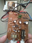
Here is a picture of the board:

Bilde014.jpg
 
Last edited:

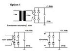
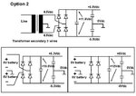
Does the mains transformer secondary has 2 or 3 wires.

power supply options are .....

Power_Batt_option1.jpg

Power_Batt_option2.jpg
 
Last edited:
I don`t understand so much of schematics... Should I solder two wires from a 12v battery on the biggest capasitor?
 

Check this first , before doing something
Does the mains transformer secondary has 2 or 3 wires.
 

If the "transformer secondary" is the little heavy box in the bacground on the picture, it has 2 black wires...
 

Ok , 2 wires from transformer.
and measured voltage in bigger capacitor was 11.8V.
Then disconnect those 2 wires from circuit board to transformer.
and connect battery with voltage 12Vdc to capacitor solder points.

Battery MUST HAVE right polarity.
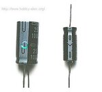
Capacitor have marks for plus or minus.

In the photograph here, the mark indicating the negative lead of the component can be seen.
You need to pay attention to the polarity indication
so as not to make a mistake when you solder battery wires.

Capacitors_2012_04_07.jpg
 
  • Like
Reactions: tpetar

    tpetar

    Points: 2
    Helpful Answer Positive Rating
Okey, I`ll try that. Thank you very much! :-D
 

Status
Not open for further replies.

Similar threads

Part and Inventory Search

Welcome to EDABoard.com

Sponsor

Back
Top