Continue to Site

Welcome to EDAboard.com

Welcome to our site! EDAboard.com is an international Electronics Discussion Forum focused on EDA software, circuits, schematics, books, theory, papers, asic, pld, 8051, DSP, Network, RF, Analog Design, PCB, Service Manuals... and a whole lot more! To participate you need to register. Registration is free. Click here to register now.

how to simulate the power of pierce crystal oscillator

Status
Not open for further replies.

xianweng

Member level 1
Joined
Aug 26, 2011
Messages
33
Helped
0
Reputation
0
Reaction score
0
Trophy points
1,286
Activity points
1,535
hi,
because the current is not a constant,somebody told me add a RC filter at the VDD and thus it is average current,
i want to know if this method is right to simulate the power and why?


thank you very much in advance
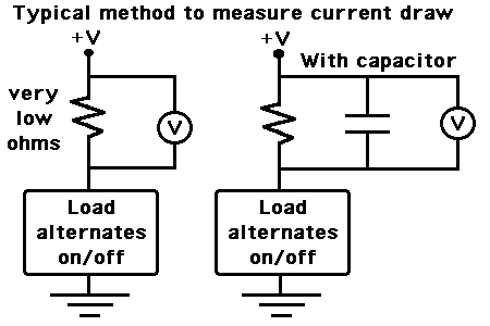
 

Assuming the following is what you're describing...

The typical way to measure current draw (besides using a plain ammeter) is to put a low ohm resistor in the power supply. Measure volts across it using a voltmeter or oscilloscope. If the frequency is more than a few Hz, the meter will average the pulses.

We wonder, will it work to install a capacitor, expecting it to average the pulses for us?

Below are schematics to illustrate.

11_1333568616.gif


Outcome:

When current is on, the capacitor will start charging. Eventually it reaches the peak value across the low ohm resistor.
As soon as current is off, it will discharge through the low ohm resistor.

The scope (or meter) will indicate a smoothed DC reading, with ripple.

As to how high will be the reading, and how much ripple...

It is based on a variety of factors.
Such as:
* capacitor value
* value of the low-ohm resistor
* draw through the load
* pulse rate of load
* duty cycle of load
* load waveform
etc.

There are so many factors which can affect the reading, in unpredictable ways.
It may be useful chiefly to indicate whether overall current draw is increasing or decreasing.
 

thank you for your reply
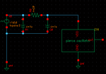
what i mean is like below schematics
QQ截图20120121143338.png
i add a RC filter to make current constant ,is this constant current average power
 

The capacitors have the effect of filtering the supply. They filter high-frequency transients, since their values are small. They do not specifically affect the resistor.

If you connect a voltmeter across the low ohm resistor, the meter movement will show a steady reading (if the oscillations are above 10 or 20 Hz).

It will show an averaged reading. It may not be the correct reading by the numbers on the scale. The meter scale is not calibrated for pulses.
 
"It will show an averaged reading."
Does this mean when i use wavescan to view the current through the V0 ,it display the average power?

---------- Post added at 16:32 ---------- Previous post was at 16:26 ----------

"It will show an averaged reading."
Does this mean when i use wavescan to view the current through the V0 ,it display the average power?
 

In ADE you can probe the VDD pin (the red square) directly, and after a transient analysis you can waveplot the current through this pin. With help of the calculator you can integrate the current and divide by the transient time -- or just print its average.
 
Status
Not open for further replies.

Part and Inventory Search

Welcome to EDABoard.com

Sponsor

Back
Top