Marat86
Junior Member level 1
- Joined
- Mar 6, 2012
- Messages
- 18
- Helped
- 22
- Reputation
- 44
- Reaction score
- 22
- Trophy points
- 1,283
- Location
- Belarus, Minsk
- Activity points
- 1,380
Hello!
I need your advice.
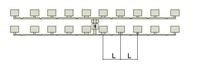
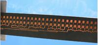
Design microstrip array is shown on this image.
Here linear symmetric phase error grow at boundary of frequency range. It leads to distortion of the main beam.
[url=http://obrazki.elektroda.pl/85_1333006268.jpg]
My question: how to feed the array to reduce the linear phase error?
Thank you.
I need your advice.
Design microstrip array is shown on this image.
Here linear symmetric phase error grow at boundary of frequency range. It leads to distortion of the main beam.
[url=http://obrazki.elektroda.pl/85_1333006268.jpg]
My question: how to feed the array to reduce the linear phase error?
Thank you.