Continue to Site

Welcome to EDAboard.com

Welcome to our site! EDAboard.com is an international Electronics Discussion Forum focused on EDA software, circuits, schematics, books, theory, papers, asic, pld, 8051, DSP, Network, RF, Analog Design, PCB, Service Manuals... and a whole lot more! To participate you need to register. Registration is free. Click here to register now.

IGBT turn on transient issue

Status
Not open for further replies.

yfluo2004

Junior Member level 1
Joined
Dec 15, 2008
Messages
18
Helped
0
Reputation
0
Reaction score
0
Trophy points
1,281
Activity points
1,447
Hi,

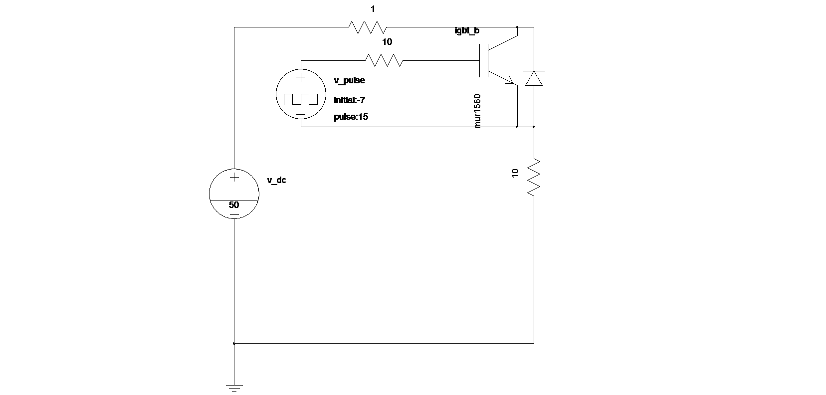
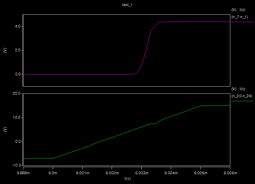
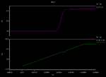
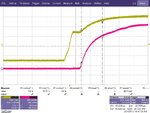
I am a beginner on IGBT. I met a problem when I verify the IGBT turn on threshold with measurement. From the theory, in the turn on transient, the driver circuit charges Cge in the beginning so that Vge increases. As Vge reaches Vth, Ic begins to increase, then because of the Miller capacitance of Cgc, Vge will maintain its value for some time (the miller plateau). Finally, Vge will increase further and the IGBT is fully turned on. This means IGBT will turn on before it enters the miller plateau.
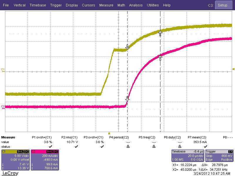
However, in my measurement, the Ic actually begins to increase after the Vge almost comes out of the miller plateau instead of before that. I use a voltage source across Vce with some small value as 10V, and the gate driver output is a step between -7V and 15V.

Can someone help me figure out where is the problem?

Thanks a lot!

YLuo
 

I guess, your terminology, for Cge is Cgs and Cgc is Cgd.
You can notice maximum miller capacitance effect when IGBT transistor enters the saturation region. In this region your transistor can be expected to give gain greater than unity. This makes your Cgd significantly high at the gate of IGBT.
During your simulation you can see the drop in the input-output characteristics.
 

Keep in mind that you'll a bit of miller plateau even with no miller effect, due to inversion of the gate channel, which makes the small signal capacitance increase near Vth. At least I know this can be observed in MOSFETs, and I assume it will happen in IGBTs as well to an extent.

I'm not really certain how device manufacturers actually measure the Qg vs Vg curves. But I highly doubt they do it with the drain voltage fixed.
 

I guess, your terminology, for Cge is Cgs and Cgc is Cgd.
You can notice maximum miller capacitance effect when IGBT transistor enters the saturation region. In this region your transistor can be expected to give gain greater than unity. This makes your Cgd significantly high at the gate of IGBT.
During your simulation you can see the drop in the input-output characteristics.

Thanks Varunkant2k. So, you mean larger miller capacitance is observed when IGBT enters the saturation region, and thus it takes longer time to charge Cgc and maintain Vge. This make sense. But since Vge will first reach Vth and the IGBT can conduct Ic before it enters the miller plateau, I do not know why in my measurement, the Ic actually conduct current after the miller plateau. This does not make sense because the Miller effect should happen after the IGBT conduct Ic and the output start to drop. Is there anything wrong with my measurement?

Thanks,

YLuo
 

Please show the schematic setup , that will be helpful. One question, why do you think, Miller effect should happen after the IGBT conduct Ic?
 

Please show the schematic setup , that will be helpful. One question, why do you think, Miller effect should happen after the IGBT conduct Ic?

The schematic is attached, the simulation waveform shows that the Ic (the top one is the voltage across a 1Ohm resistor which represent the current)begins to increase before the Miller plateau, while the measurement shows the Ic begins to increase after the Miller plateau. I think the drive current first charge Cge and Cgc, after Vge reaches Vth, the IGBT conducts and Vce starts to decrease, this time the Miller capacitance increases a lot and the Vge maintains some time until the Miller capacitance is charged. So, the Miller effect should be significant after the IGBT conducts. That's why I think the Ic should increase before the Miller plateau. Is that correct?

Thanks,

YLuo


Attachments

  • edaboard_sch.png
    edaboard_sch.png
    14.3 KB · Views: 121
  • edaboard.png
    edaboard.png
    8.6 KB · Views: 113
  • 1500-150pi11.JPG
    1500-150pi11.JPG
    70.2 KB · Views: 116
Last edited:

YLuo, you are right. See the image below.
Miller_Plateu.JPG
I doubt the simulation result, because model file you are using for IGBT transitor, may not be correct.
 

Please check your test bench, at the gate applied pulse should not be across Vge but Gate to ground.
 

- The measurement setup isn't clear, how C1 and C2 are exactly probed?
- There may be a delay skew between involved probes as well as an arbitrary skew added in the oscilloscope setup. You should verify, that both measurements are actually in phase.
 

Status
Not open for further replies.

Similar threads

Part and Inventory Search

Welcome to EDABoard.com

Sponsor

Back
Top