muhammadali_16
Full Member level 3
Hiz.
how r u all?
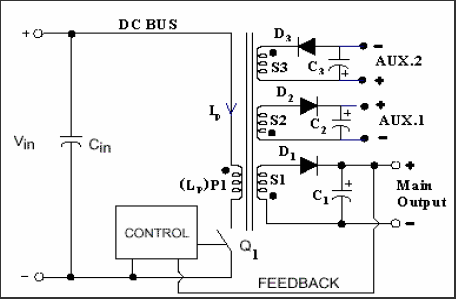
i want some help regarding SMPS. im using PUSH-PULL terminology to make 12Volts.
i want multiple output voltages. +12V, 5V and 3.5V.
kindly tell me any terminology to do this.
thx
how r u all?
i want some help regarding SMPS. im using PUSH-PULL terminology to make 12Volts.
i want multiple output voltages. +12V, 5V and 3.5V.
kindly tell me any terminology to do this.
thx
")