bleach786_fan
Newbie level 4
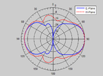
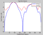
The attached photo is that of a field pattern for a yagi antenna.Result of a graph when running the code from balanis on Yagi_Uda.m. My problem is that I cannot understand the graph that I am having.I understand that it is a plot of E-field agains theta and H-field against phi. But I cannot interprete the result obtained.??
I would also like to know if there is a way to know the directivity, E-plane and H-plane at half-power beamwidth from just those graphs??
The directivity obtained was 8.68 dB and the E-Plane and H-plane was 48.3 and 55.1.:?:
I would also like to know if there is a way to know the directivity, E-plane and H-plane at half-power beamwidth from just those graphs??
The directivity obtained was 8.68 dB and the E-Plane and H-plane was 48.3 and 55.1.:?: