ali kotb
Member level 3
i need to design subthreshold mosfet as 1M ohm resistance connected to other mosfet gate
here is the ct attached
M7, M9 should be in subthreshold , but i dont know how to design it
can any one help
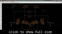
here is the ct attached
M7, M9 should be in subthreshold , but i dont know how to design it
can any one help
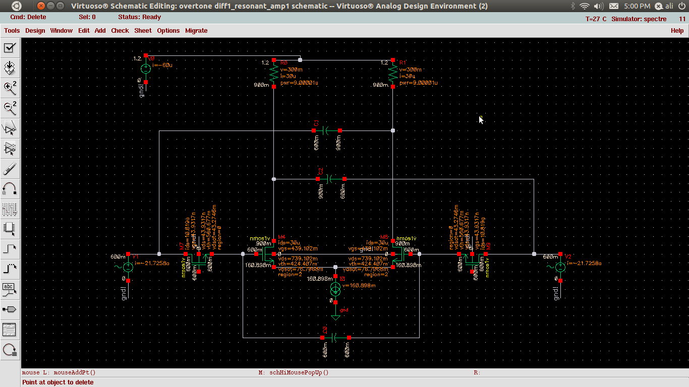
") it was just the values from previous simulations.
it was just the values from previous simulations.