Continue to Site

Welcome to EDAboard.com

Welcome to our site! EDAboard.com is an international Electronics Discussion Forum focused on EDA software, circuits, schematics, books, theory, papers, asic, pld, 8051, DSP, Network, RF, Analog Design, PCB, Service Manuals... and a whole lot more! To participate you need to register. Registration is free. Click here to register now.

90 degree phase shift for a wide range of frequency ( exactly , 90 degree !)

Status
Not open for further replies.

goldsmith

Advanced Member level 6
Joined
Dec 14, 2010
Messages
3,981
Helped
741
Reputation
1,486
Reaction score
726
Trophy points
1,413
Location
Tehran - IRAN
Activity points
24,546
Dear All
Hi
Thank you for your time .
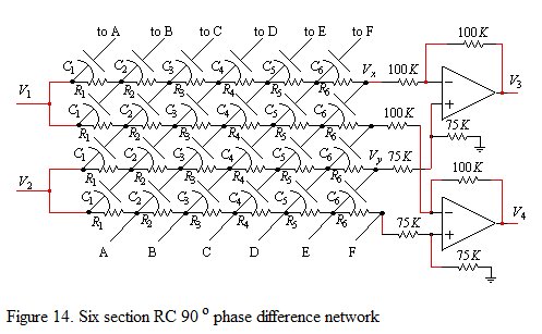
I know how can i create 90 degree phase shift for an specific frequency , but how to create it for a wide range of frequency ?
Thanks in Advance
 

In the analog domain, a differential phase shift between two all-pass chains is the only available means. It has been discussed previously at Edaboard, the latest in this recent thread. Please refer to the first link in post #9.
https://www.edaboard.com/threads/241020/#post1032377

In digital signal processing, a Hilbert transformation can be approximated in a restricted frequency range by a FIR filter. As all FIR filters, it involves an additional signal delay.

Referring to the question title, neither the analog nor the digital wide band phase shift are exact by nature. They are approximations with a ripple depending on the implementation effort.
 
Dear FvM
Hi
Thank you for your reply .
I'll read that thread completely , and tell the result .
Appreciate
Goldsmith
 

It depends on the frequency but for RF I think one method uses transformers
Besides different circuit technologies available for audio or RF frequencies, it mainly depends on the meaning of "wide range". The principle problem of generating an "exact" wide range phase shift is basically the same. There are additional means provided by distributed circuits, but they are also approximations of an ideal 90° shift in some regard.
 
The amount of phase change is directly related to the time constant. (R*C, or L/R).

As long as there is any amount of series resistance, the amount of phase change will never reach 90 degrees, in either a capacitor or coil.

Current lead is built into the way a capacitor behaves when exposed to a sine wave. At 3/4 cycle the charged capacitor starts discharging into the falling sine wave.

By the same token, current lag is built into the nature of an inductor exposed to a sine wave.

With any given capacitor or inductor, you can increase the phase change by lowering the series resistance.

If you could achieve zero resistance, then phase change would be minus 90 degrees for every capacitor, and plus 90 degrees for every inductor, at every frequency.

Of course this is not possible with real components. A real coil has some ohmic resistance and some capacitance.

A real capacitor has some ohmic resistance and some inductance. In general, capacitors yield more 'purity' of response.
 
Heya Goldsmith (et al)!

I 've needed broadband 90 degree phases shifts on a number of occasions, and I've had a *great deal* of success with a configuration I first dicovered in the ARRL Handbook, and described in detail (in the "The Phasing Method of Image Rejection" section) of https://michaelgellis.tripod.com/mixerscom.html.
[I've reproduced it here for convenience:]
74_1331816815.jpg


Although it's often discussed in the context of audio-band (300 Hz - 3 kHz) phase shifting, I obtained the original paper describing its operation [Saraga, W., "The Design of Wide-Band Phase Splitting Neworks," Proc IRE, Vol 38, p 754 (1950)] and coded the equations into the following MATLAB script:


Code C - [expand]
1
2
3
4
5
6
7
8
9
10
11
12
13
14
15
16
17
18
19
20
21
22
23
24
25
26
27
28
29
n      = 6;           % Number of RC stages within network
fLower = 1000000;     % (Hz) - Lower network design frequency
fUpper = 10000000;    % (Hz) - Upper network design frequency
R      = 220;         % (Ohms) - Value of resistance used throughout the network
 
m = 1 - (fLower/fUpper)^2;
K = ellipke(m);
 
for i = 1:n
    [sn, cn, dn] = ellipj(((2*i - 1)*K)/(2*n), m);
    RC(i) = dn/(2*pi*fLower);
end
 
C = RC/R;
fprintf('For a %d Hz - %d Hz %d stage RC network (R = %d), Cn is as follows:\n\n', ...
fLower, fUpper, n, R); 
for i = 1:n
    if (C(i) < 1e-9)
        fprintf('C%d = %6.2f pF\n', i, C(i)*1e+12);
    elseif  (C(i) < 1e-6)
        fprintf('C%d = %6.2f nF\n', i, C(i)*1e+9);
    elseif  (C(i) < 1e-3)
        fprintf('C%d = %6.2f uF\n', i, C(i)*1e+6);
    elseif  (C(i) < 1)
        fprintf('C%d = %6.2f mF\n', i, C(i)*1e+3);
    else           
        fprintf('C%d is physically unrealisable!\n', i);    
    end
end


As the script suggests - I've successfully built a 1 MHz - 10 MHz network using this approach! I used this as a part of an image-rejecting HF mixer design and I recall obtaining +/- 2 degree phase accuracy over the design bandwidth. This figure can apparently be improved with more stages, but I haven't personally tried this since the level of accuracy obtained was sufficient for my application.

I built a second version operating at a few 100 kHz a while later, with similar success.

So that's the LF stuff - for the microwave end of the spectrum, you cant go past a stripline "quadrature hybrid coupler" (descibed here: **broken link removed**) for simplicity and performance. I've found that EM simulation and optimisation (with ADS, CST etc) is essential for best performance, as is constructing them on a predictable substrate (e.g. Rogers instead of FR-4). I've made 2.4 GHz devices with 1 GHz bandwidths this way with little difficulty, and even had modest success with nothing more than a teflon-substrate PCB blank and a scalpel, cutting around the outline of a printed template!

Good luck :)
 
Dear thylacine1975,
Thanks a ton. This is exactly what we were looking for. Also, as an aside, we have now ordered a copy of the ARRL Handbook.

As another aside, this is probably the most helpful forum post I've ever come across. Who includes MATLAB code in a comment?! You do.

Thanks again,
Brandon
 

It occurred to me a while ago that you could make a good low frequency wideband phase shifter by upconverting the signal to RF, using a relatively narrowband phase shifter, then downconverting back again. So a 1MHz bandwidth at 100MHz (easy to do) would become a 100Hz-1.1MHz bandwidth (crazy). Has anyone tried this? It would be pretty complicated and would require full image rejection, but in principle I can't see why it wouldn't work.
 

I've seen/heard of similar things being done. For example, this technique was used enable the use of COTS variable phase shifters in bands where COTS phase shifters don't exist. I haven't heard about it for lower frequency, like you're proposing, but I haven't really worked below ~200MHz before now.
 

Status
Not open for further replies.

Similar threads

Part and Inventory Search

Welcome to EDABoard.com

Sponsor

Back
Top