Continue to Site

Welcome to EDAboard.com

Welcome to our site! EDAboard.com is an international Electronics Discussion Forum focused on EDA software, circuits, schematics, books, theory, papers, asic, pld, 8051, DSP, Network, RF, Analog Design, PCB, Service Manuals... and a whole lot more! To participate you need to register. Registration is free. Click here to register now.

[SOLVED] 741 Op-Amp in non-inverting state for amplification for guitar distortion effect

Status
Not open for further replies.

DelsonNomad

Newbie level 4
Joined
Mar 13, 2012
Messages
7
Helped
0
Reputation
0
Reaction score
0
Trophy points
1,281
Activity points
1,345
I have had a slight problem recently where I haven't been able to get this circuit, for a guitar distortion effect, to work (the circuit is attached)

I would like the LM 741 Op-amp to use a 9V DC PP3 power source (with +/- 4.5V as power rails) and have a gain of 100 that is varied with the potentiometer to change the amount of signal that is directed to the non-inverting pin. Is this possible with this op-amp?

I have made a schematic of the circuit and bread-boarded it but it doesn't work ... could anyone please help? It would be a big relief for me because I would really like to fix this ! :)

If you could, could you please tell me where specifically ground is and where I would put ground on a bread-board? I am quite new to this form of electronics. It would be absolutely fantastic if you could tell me what is wrong with the circuit and ways in which I could improve it...

Thank you in advance! Initial Idea 1.png
 

May be there are some other errors - however, at first sight I have discovered that a ground connection is missing BETWEEN both 9 volt supplies.
Try it - perhaps then it works .

---------- Post added at 12:20 ---------- Previous post was at 12:16 ----------

As a second error: The non-inv. opamp input needs a dc connection to ground (bias current).
 
Small fixes...
-GND point AC-connection with capacitors 2pcs 10µ
-non-inverted input bias via 47k
-invert input short to -V removed
-output serial resistor 4.7k added
-output capacitor smaller value

all added components values are not exact.

GuiDistor741.jpg

Some additional info...
Cook your own distortion
Making your own distortion design is easy. So why not design your very own distortion effect?
**broken link removed**
 
Last edited:
To LvW

Thank you for your post :)

I am only using one 9V battery in this schematic and then two 1K resistors as a potential divider to 'create' a +4.5V rail before the first resistor, a 0V / ground rail between the resistors and a -4.5V rail after both resistors..
Therefore, I don't really understand what you mean by that particular ground connection... You could please reply about what you mean?

However, thank you very much for your suggestion about the bias current - I will alter my circuit :)

---------- Post added at 16:33 ---------- Previous post was at 16:24 ----------

Thank you so much for your post :)

I have checked out the website and it has helped greatly.

I will post to the thread after I have made the changes that you and LvW have suggested.

Thank you kak111

From Damon
 

To LvW
I am only using one 9V battery in this schematic and then two 1K resistors as a potential divider to 'create' a +4.5V rail before the first resistor, a 0V / ground rail between the resistors and a -4.5V rail after both resistors..
Therefore, I don't really understand what you mean by that particular ground connection... You could please reply about what you mean?
..............

Hi Damon, everything OK - I have overlooked (at first sight) the potential divider that creates two separate supplies.
LvW
 
Okay :) thank you very much for your post! No worries ;)

Damon
 

The exact behaviour of the virtual ground voltage divider is hard to predict. Because the OP output is shorted by diodes, the virtual ground is very unstable. You would want to provide at least a lower impedance virtual ground, e.g. by adding a complementary voltage follower or zener clamp.

In addition, you'll notice that the switch matrix can't work as sketched, because all pathes are shorted against each other on the output side.
 
After analysing my circuit again I realise what you say about the output of the Op Amp... thank you for notifying me to this :)

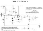
I understand what you mean when you say the virtual ground is unstable and I've compared it to other circuits, like the 'mxr distortion plus circuit schematic', and this has brought to my attention that a potential divider is actually not used by other circuits that offer distortion too... i wonder why this would be and how they solve the issue of a double polarity power source. I've attached the mxr distortion plus circuit schematic.

Thank you very much for you post ;) mxrdistp.gif
 

Thank you very very much for this useful post! I will check my modified circuit with these ones ;)

---------- Post added at 18:55 ---------- Previous post was at 18:54 ----------

To Kak111
Thank you very very much for this useful post! I will check my modified circuit with these ones ;)
 

A little bit out of topics,
tested and working PC programs for guitar - & other analog signals

GuitarFX is freeware now! No money needed!
It works for free without money!
Thanks to our sponsor!

Download and use for free:
**broken link removed**

http://guitarfx.info/

http://guitarfx.net/

Creating Professional Guitar Sound on PC
**broken link removed**

...................................................................

MULTI-TRACK RECORDERS for FREE
...................................................................

KRISTAL Audio Engine is a powerful multi-track recorder, audio sequencer and mixer - ideal for anyone wanting to get started with recording, mixing and mastering digital audio.
It is designed as a modular system. The main application provides a mixing console, while the audio sequencer, live audio input and so on are loaded as separate Plug-Ins.

LICENSING
KRISTAL Audio Engine is free for personal, educational and non-commercial use.

KRISTAL Audio Engine

16 audio tracks
32 Bit floating point audio engine
44.1 to 192 kHz sample rate*
Downmix to 16/24/32 Bit audio files
3-band parametric EQ &
2 VST insert slots per channel
3 VST master effect slots
ASIO low latency audio driver support
4 KRISTAL Plug-In slots
Load/Save KRISTAL project files
Supported file formats: WAVE, AIFF, FLAC, OGG Vorbis

The following Plug-Ins are included in the KRISTAL package:

KRISTAL Waver

the sequencer Plug-In for KRISTAL
multichannel harddisk recording via ASIO/MME
ASIO input monitoring
audio clip arrangement
audio clip fade-in/fade-out/crossfade
unlimited undo/redo
AES31 Export

KRISTAL LiveIN

connect your mic/guitar and play thru KRISTAL using VST effects in realtime

KRISTAL Effects Plug-Ins

KristalMultiDelay
KristalChorus
KristalReverb
Kristalizer

KRISTAL supports VST effects Plug-Ins to be used as 'inserts' in each audio channel and in the master section of KRISTAL mixer.

Effects can be used to influence the sound of the recorded audio material in a song. Typical effects include e.g. Reverb, Chorus, Flanger, Distortion,... etc.

VST (Virtual Studio Technology) is a proprietary 'industry standard' for audio effects Plug-Ins, developed by Steinberg Media Technologies GmbH. There are hundreds of compatible Plug-Ins (free and commercial) available on the web. A good place to look for is e.g. http://www.kvr-vst.com/


http://www.kreatives.org/kristal/index.php?section=details

.........................................................................................................

AUDACITY , the free, open source, cross-platform audio editor.

Recording

Audacity can record live audio through a microphone or mixer, or digitize recordings from cassette tapes, records, or minidiscs. With some sound cards, Audacity can also capture streaming audio.

Record from microphone, line input, USB/Firewire devices and others.
Device Toolbar manages multiple input and output devices.
Timer Record and Sound Activated Recording features.
Dub over existing tracks to create multi-track recordings.
Record at high sample rates in excess of 192,000 Hz (subject to appropriate hardware).
Record multiple channels at once (subject to appropriate hardware).
Level meters can monitor volume levels before, during and after recording. Clipping can be displayed in the waveform or in a label track.

Effects

Change the pitch without altering the tempo (or vice-versa).
Remove static, hiss, hum, or other constant background noises.
Alter frequencies with Equalization, Bass Boost, High/Low Pass and Notch Filter effects.
Adjust volume with Compressor, Amplify, Normalize and Fade In/Out effects.
Remove Vocals from suitable stereo tracks.
Create voice-overs for podcasts or DJ sets using Auto Duck effect.
Other built-in effects include:
Echo
Phaser
Wahwah
Reverse
Truncate Silence

Plug-ins

Add new effects with LADSPA, Nyquist, VST and Audio Unit effect plug-ins.

Effects written in the Nyquist programming language can be easily modified in a text editor - or you can even write your own plug-in.

http://audacity.sourceforge.net/
 

Your 741 V- terminal is connectecd to Vin - input terminal pin 2 ...And the 1Kohm is between the Gnd and V-...As such , V+ to gnd is 1Kohm but V- to gnd is only 500 Ohm. thus supply across OPA is biased at 7.5VDC on + side and 2.5V to minus .The negative sided swing of the data has onesided clippings and bounds with a distorted signal.
 

Instead of using a 1K/1K divider for balancing of the +/-4.5VDC from a 9V battery ,,,use a pair of 220/100ufd/25VDC capacitors across it..The series combination center is put to common ground and you get a balanced bipolar voltage...for correct balancing of the OPA..
 

Instead isn't actually a good idea. DC balancing would be still required. As the fuzz guitar effect is basically an AC circuit, input and output AC coupling, as used in all simple effects I've ever seen, seems more appropriate.
 

Thank you very much vimalkhanna and FvM for your posts -> i have made some modifications and I have tested whether the AC coupling or the combination of two capacitors works better.. In this circumstance, the AC coupling works a treat but the caps don't

Thank you both for your posts - I'm pretty sure everyone on this part of the forum have solved all the issues with the circuit.. Thank you ALL very very much!! :D
 

Thanks for feedback.However , what is your problem regarding input coupling capacitor???The opamp input can be 1Megohm for which the coupling caps can be 100ufd .This will give a 1Hz as input 3dB cutin..Do you want the same to be lower still??/
 

Oh... Okay i get it ;) well actually it's fine there must have been a different issue :/
No no, thank you ;) all is well

Thank you vimalkhanna ;) you have been very helpful :)
 

Status
Not open for further replies.

Similar threads

Part and Inventory Search

Welcome to EDABoard.com

Sponsor

Back
Top