Continue to Site

Welcome to EDAboard.com

Welcome to our site! EDAboard.com is an international Electronics Discussion Forum focused on EDA software, circuits, schematics, books, theory, papers, asic, pld, 8051, DSP, Network, RF, Analog Design, PCB, Service Manuals... and a whole lot more! To participate you need to register. Registration is free. Click here to register now.

Need help w 12 VDC power supply design

Status
Not open for further replies.

vanchopski

Newbie level 4
Joined
Mar 8, 2012
Messages
5
Helped
0
Reputation
0
Reaction score
0
Trophy points
1,281
Activity points
1,330
I'll just let everyone here know first off that I'm a complete rookie at electronics which is exactly why I'm here requesting help with what for you folks is likely a simple project design.

I'm desinging a prototype device that I hope will improve the performance of a kitchen appliance. The prototype includes a microprocessor that controls both the appliance and an external device.

I'm hoping to be able to power the microprocessor and the device both from the appliance's power supply.

- the microprocessor requires 5 VDC @ 1A but has an onboard regulator that can handle up to 12 VDC
- the external device requires 12 VDC at 25 mA

I found a schematic that supplies 9 VDC from 120 VAC input and I was wondering if it could be easily modified to supply 12 VDC @ 1A.

Info on the main components:

- Hammond 161D12 transformer, Series output 12.6 VAC @ 70mA, Parallel output 6.3 VAC @ 140 mA
- B80C800G bridge rectifier, https://pdf1.alldatasheet.com/datasheet-pdf/view/61892/GE/B80C800G.html
- 7809 voltage regulator, **broken link removed**

Can anyone explain what would have to be altered with this design?
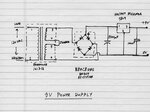
 

Attachments

  • 9Vpsu.jpg
    9Vpsu.jpg
    46.8 KB · Views: 79

Hi dear vanchopski
Yes , you can !
You have some ways :
1- try to use some resistors at ground of that regulator and out put of of that to increase it's voltage .
2- try to change 7809 to 7812 and add a transistor .
and ....etc.
So , to select the proper way , tell , me , that what is the out put of your transformer ( it's AC out put ) .
Best Wishes
Goldsmith
 

Thanks Goldsmith! I appreciate the input.

1 - Can you explain what value resistors I'd need to use with the regulator? Are you saying both the ground and output would require resistors?

2 - What spec/type transistor would I need to use and where does it go?

3 - the output of the transformer: Series output 12.6 VAC @ 70mA, Parallel output 6.3 VAC @ 140 mA

4 - I've just done a bit of reading on the 78XX voltage regulators. Is using a 7812 a concern here re: heat production? Is there a better way to do this using a switching regulator?


1- try to use some resistors at ground of that regulator and out put of of that to increase it's voltage .
2- try to change 7809 to 7812 and add a transistor .
and ....etc.
So , to select the proper way , tell , me , that what is the out put of your transformer ( it's AC out put ) .
 
Last edited:

A switching regulator is certainly an option but your transformer current rating is too low for this. It needs to be rated at no less than the maximum current you want to draw from the circuit and preferably more to add a safety margin. You present transformer, aside from insufficient current, is also perilously low on voltage. One rated at 15V AC, 1.5A would be more suitable.

Basically:
if you want to regulate a voltage down using a 7812, you must have at least 3V more at it's input pin, in other words 15V.
You can regulate up or down using switching regulators but the circuit is a little more complicated and you need inductors and fast switching diodes which cost more than a 7812.

If you are starting from scratch, why not directly generate a regulated 5V for the processor. Generating 12V then dropping it again is less efficient.

Brian.
 

Again Hi
As Brian said , you can use switch mode regulators such as lm2576 too , but in your original question :
see below please :

View attachment datasheet.pdf

You can find things that you want at the end pages of that .
BTW as Brian said the problem is this that your transformers current is low .
best Wishes
Goldsmith
 

Thanks betwixt and goldsmith.

I need 12 VDC to power both the board and the external actuator so it seemed simplest to feed 12 VDC to both and let the regulator onboard the microprocesser handle dropping the 12V to 5V.

I'd definitely consider starting from scratch. Because I'm a rank beginner at this I just grabbed that schematic because it seemed close and I thought it might be simple to change a couple of components to get what I needed.

I'll give your ideas some thought!

Chops
 

OK so as a more appropriate transformer would this work? **broken link removed**

Goldsmith I looked the the data sheet you linked to and I'm guessing you're referring to Figure 17 on page 26? So that schematic shows:
- a KA78XX fixed regulator
- D45H11 transistor
- resistors of 0.5 Ω, 4.7 Ω and 470 Ω
- capacitor at .33 µF
- a diode
- a zener diode
- an inductor
- a couple of special looking capacitors

Are these all components that would be required in addition to the transformer? Just wondering this because it occurs to me that the inductor might be part of a transformer too.

And as far as switching vs fixed regulators do I have this right:

- a switching regulator is just a fixed regulator with additional components and is therefore a little more expensive to set up and requires more space?
- a fixed regulator is simpler and cheaper but will waste more power to heat?

Any other factors to consider?
 

Again Hi
Advantages of linear regulators are : easy to design . easy to change the out put voltage ( fast ) . at low powers cheap .
And disadvantages : 1- large power dissipation . 2- large capacitors as bulk . 3- large transformer required . 4- non economical ..... etc
And about SMPS ( switch mode regulator ) : cheap . compact design . can designed without iron core transformer . low value of bulk capacitor and compact filters . bad noises and spikes at out put ( but with some other filters we can solve this problem ) . EMI ( electro magnetic interference or RFI , (radio frequency interference )) but can improved by line filter at the input of main power line . and .... etc .
And about that inductor that you can see at datasheet : the designer , changed that simple regulator to a switching regulator simply.
And it is independent inductor .
Good luck
Goldsmith
 

OK thanks again. I think I understand now.
 

Your transformer (6.3 VAC @ 140 mA = .88VA) is seriously underpowered. You need 5W min, 5 VDC @ 1A
Consider main PS = 5Vdc . verify V-I needs again.
The diode bridge is also under-rated. 0.8A continuous.
 

Status
Not open for further replies.

Part and Inventory Search

Welcome to EDABoard.com

Sponsor

Back
Top