TXRX
Full Member level 2
Hi,
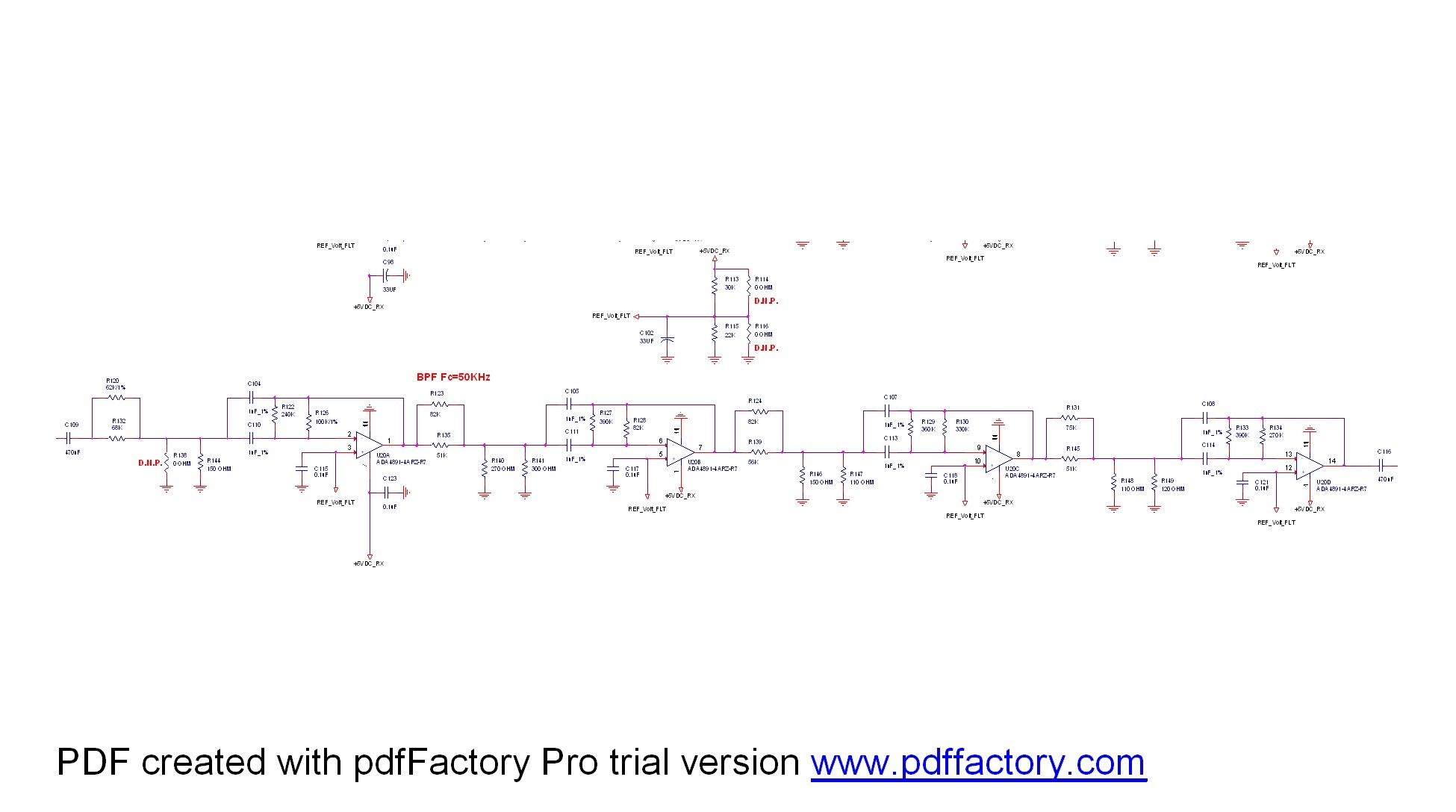
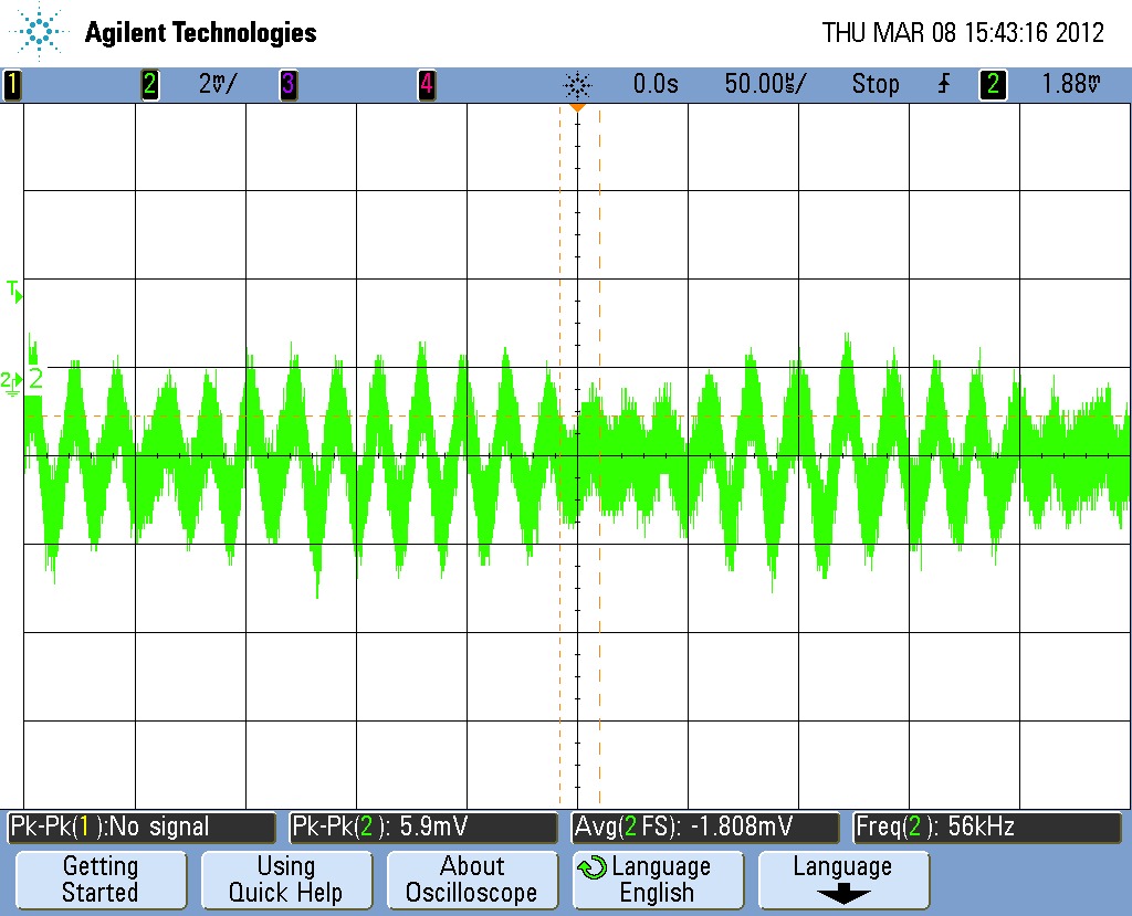
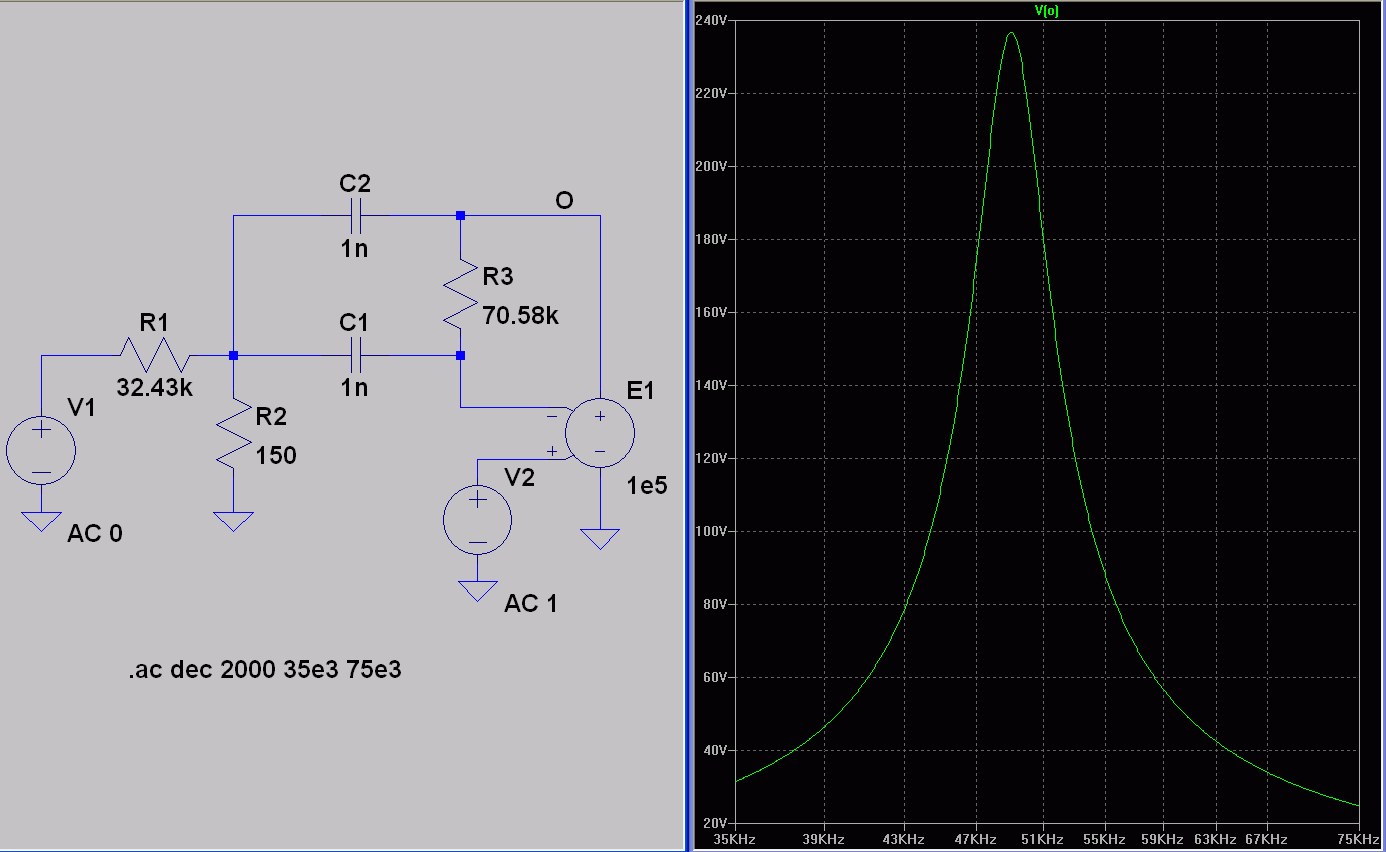
I built an Active Filter Butterworth 8 order.
I receive at the output noise of 5mVptp.
Does anyone know why i receive a very high noise at the output ?
Thanks !
I built an Active Filter Butterworth 8 order.
I receive at the output noise of 5mVptp.
Does anyone know why i receive a very high noise at the output ?
Thanks !