Continue to Site

Welcome to EDAboard.com

Welcome to our site! EDAboard.com is an international Electronics Discussion Forum focused on EDA software, circuits, schematics, books, theory, papers, asic, pld, 8051, DSP, Network, RF, Analog Design, PCB, Service Manuals... and a whole lot more! To participate you need to register. Registration is free. Click here to register now.

Workshop power supply 0-25V, 0-5A

Status
Not open for further replies.

Vermes

Advanced Member level 4
Joined
Aug 2, 2011
Messages
1,163
Helped
0
Reputation
0
Reaction score
0
Trophy points
1,316
Activity points
22,318
1621616000_1326324468_thumb.jpg


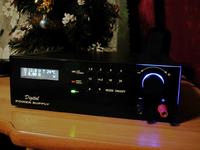
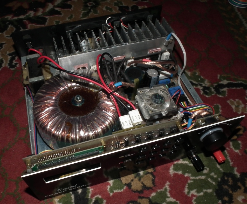
This power supply convenient way to control was improved with a rotary regulator with encoder. A single movement of the knob corresponds to the „up”, „down” buttons on the keyboard, while longer and faster turning switches to higher or lower voltage threshold with an amplitude corresponding to the buttons on the keyboard. Implementation of this part of the power supply may cause some troble becuse of the difficulty with connecting it to the processor.
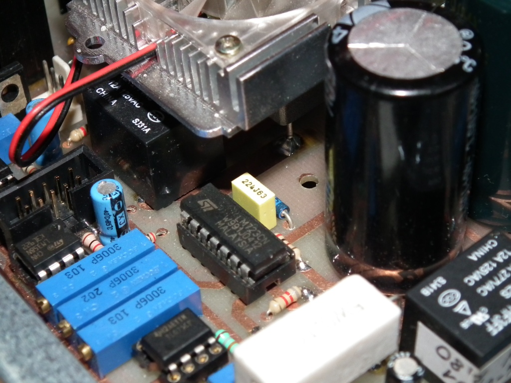
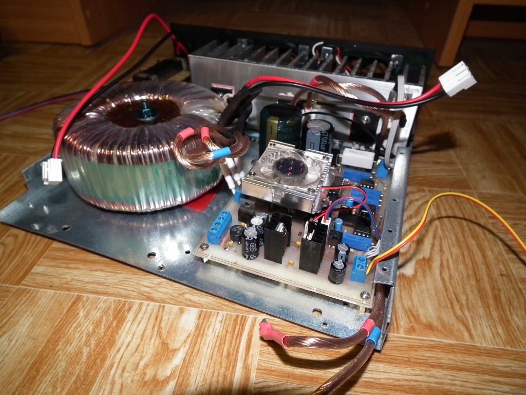
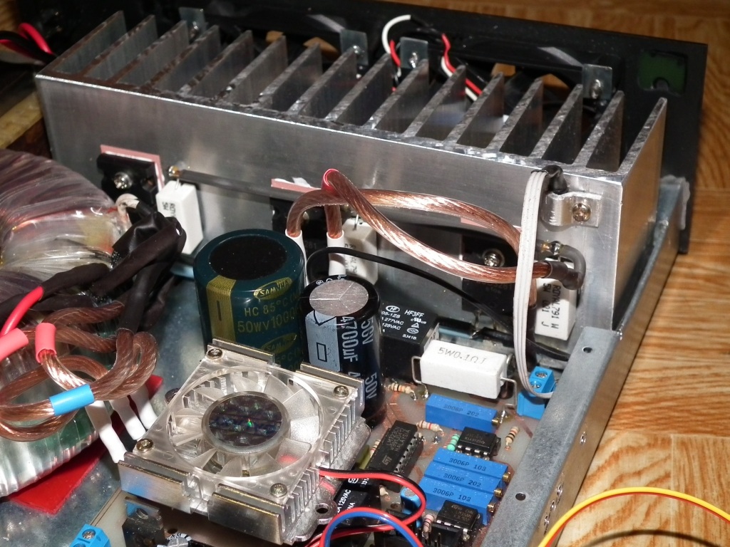
All boards of the power supply were home made. They were protected with a layer of lacquer. Paths passing to the other side were linked by a thin wire through the holes. Pins that do not connect the circuit were not soldered. It would be difficult to solder out eventual broken elements.
There was an additional module applied with processor Attiny2313, connected to the board with the power supply processor.
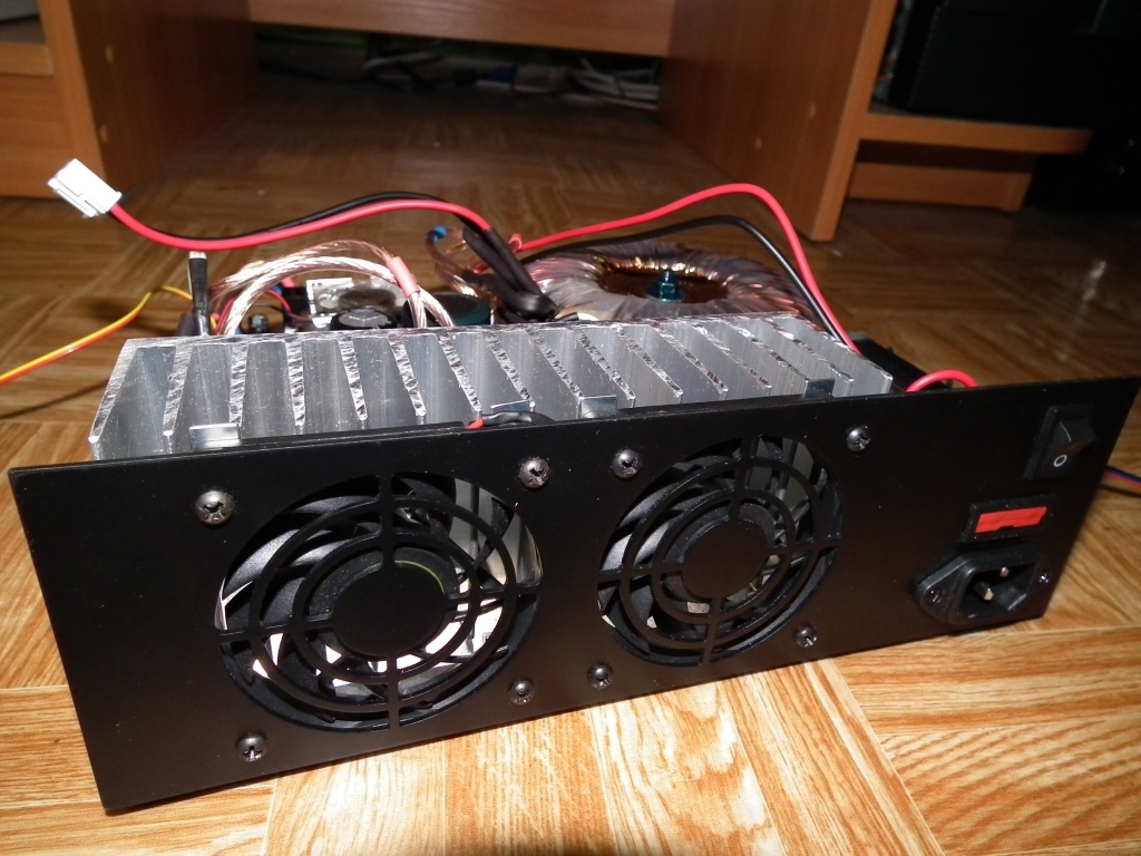
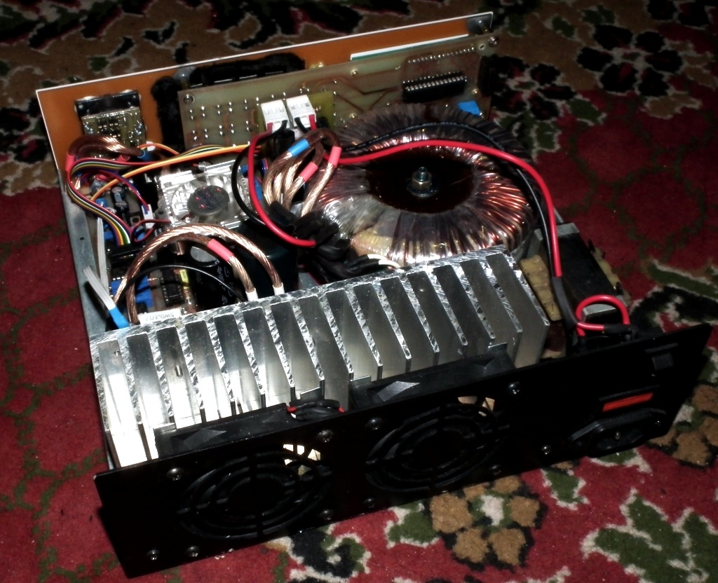
Both the front panel and the rear panel were made in the laminate using milling machine.


Link to original thread (useful attachment) – Zasilacz warsztatowy 0-25V, 0-5A
 

I can't see any schematics on this site or the original link so how could we build
 

Thanks Fragrance I will have a look

wizpic
 

Does anybody know what te pots are for I have a rough idea P!,P2,P3,P4,P5 only the documant is not in english

thanks
 

Using Google's document translation, this is the translation I got. Hope you get your answers from here:
Translated version of 3248.pdf
Page 1
24
Playboy 12/2008
Related projects
these articles are all available on CD
Title of the article
No. EP / EDW
Putty
The high stabilization workshop
EP 1/1999
AVT-1220
Symmetrical Power Supply
EP 11/1999
AVT-1253
Quad Power Supply Workshop
EP 8/2008
AVT-1477
Power Amateur
EDW 3/1996
AVT-2001
Miniature pulse stabilizer
EP 4/1996
AVT-1081
Power Supply 20V 10A 10th ..
EDW 1/2001
AVT-2462
Symmetrical Power Supply
EDW 9/2002
AVT-2624
Electronically controlled power supply
EDW 7/2003
AVT-2672
Digital Power
EDW 8/2003
AVT-2674
Power Workshop 0th .. V/0...2 25.5, 55A
EDW 7/2005
AVT-2757
Pulse stabilizer 12V 10-20A
EDW 2/2006
AVT-2779
Microprocessor Lab power supply
EP 10/2002
AVT-5083
Power-controlled
Digitally
BASIC PARAMETERS
• plates with dimensions: 184x61 mm,
104x136 mm
• Voltage adjustment range: 0 .. 25 V
• Step of voltage: 100 mV
• Adjustable current limit:
10 mA ... 5 A
• Step control current: 10 mA
• Measurement of current consumed by the power
system
• Measurement of the heat sink temperature
• Electronic thermostat with a hysteresis of 2 ° C
control the fans
• Thermal protection
• Programmable switching temperature
fan and thermal protection
in the range 0 .. 100 ° C
• Alarm output terminals short-circuit
AC
• 12-button keypad
• The disconnection of power from a powered
of
• Memory of last setting voltage and limited
Current connection
• LCD display 2x16
AVT-5161
AVT Event:
AVT-5161 - printed circuit board
There are a few iconic elements
that electronic
despite the passage of years, still
are produced and readily
applied. Older electronics
know them well, not only
of the stories, the younger and after
reading this article will
had the opportunity to find out about their
"Greatness." LM723 is a system
circuit, without whom had not
It was impossible to imagine
power supply. Flavor to the project
also used the following
m in the A741.
Recommendations:
easy to build power
with excellent performance
will be applied
in laboratories
Electronic amateur
and professional services.
Additional resources >>
obtained additional features of the microcontroller
extending the capabilities of the power supply, as well as
improving the comfort of use.
Description of the system
Construction of the power supply is divided into
two parts. Diagram of the main part of the power supply
shown in Figure 1, while in Figure 2
diagram of the control system.
Power supply used in the construction of popu-
ne and readily available components, and most important-
importantly, their price is not high. The entire system
is powered by 200 watt transformer
with dual secondary winding
2x12 V voltage rectification provides a bridge
rectifier B1, capacitors C3 and C4 filter
output voltage. They have a large capacity,
which allows to minimize the output ripple
power when downloading large currents.
Capacitor C10 shorted to ground potential
brief surge of electricity grid.
Element acting as a controller in-
voltage is produced for years and well known
all LM723 circuit. It works in some
unusual configuration. For a voltage
output of less than 2 V Application-
no reduction in ground potential by feeding
a voltage of -5 V. The on-
voltage is quite sufficient for the materials
Skåne output voltage from zero.
Because of the reduction potential of the mass,
it was necessary to use a stabilizer
consisting of a resistor R11 and diode-Zene
ra D4. When idling power supply voltage
power would exceed the maximum permissible
dispersive value of 40 V, at which LM723 circuit
HIT NUMBER
Power is the basic equipment
any design studio or the amateur
Union or professional. Professional Power
company are not cheap, unfortunately, the author decided to
So design a device, which in respect of-
large for a relatively low cost would be
alternative to them. All functions and para-
meters are set digitally using
12-button keypad. With the
________________________________________
Page 2
25
Playboy 12/2008
Digitally controlled power supply
can still work. The system contains
in a highly stable source of voltage from-
bringing that is not being used
in the illustrated arrangement. There is also
error amplifier and transistor limitations
Current. Built-in error amplifier
the structure of the LM723 operates so that the voltage
its inputs IN and NI are equal. On
one of these inputs (IN) voltage is applied
of the output divider R15, P3, R13, which
division is 1:10. If now the input NI
(Leg 5) will be given voltage 1.2 V, the
the control of a comparator output transistors,
in T3, T5, T6, to the input IN (leg 4) was
exactly the same voltage, ie 1.2 V. After-
Invalid divider has a division by 10, then the output
ściu get stabilized voltage of war-
values of 12 V. To obtain the output voltage
a value of 25 V to the input 5 state
voltage of 2.5 V. With respect to the tip 7 of the
LM723 NI input voltage will be
up to 7.5 V, and therefore does not exceed the in-
voltage 8 V - the maximum input voltage
ściach error amplifier, which is defined
by the manufacturer of the system.
Digital control of output voltage value
ściowego obtained by changing the voltage on
NI input (5) using the D / A. With
due to the simplifying power supply design
not used here expensive D / A.
We used a simple RC integrator circuit (R6,
C17), which was given a course of PWM
from the output of the microcontroller ATmega8 OC1A
and voltage follower U7 odseparowujący
integrator circuit layout from incriminating him.
Change the value corresponding to the digital
is the voltage value by the total-
CHING PWM signal, the RC circuit, which
time constant is greater than the period waveform
during PWM. D / A converter has a resolution of 10
bits, and its output voltage falls
the voltage-mikrokontrole
ra, and hence from 0 to 5 V. The smallest value
tension, a tension that will be changed
D / A converter is 5/1024 = 4.88 mV.
In the division of the output voltage by 10
divisor gives a resolution of output voltage
ściowego about 50 mV.
The output voltage is filtered by
capacitors C16, C11. An important advantage of stabilizing
Zator LM723 is that it does not impose a rump-
EQUIVALENTS restrictions on output current. This current
is dependent on the applied transistor
the output. In the described power supply are
two power transistors connected in parallel
2SC3281 (T5, T6) with resistors emiterowymi.
One transistor is able to dissipate the
150 W of power loss. This value is only possible
Possible to achieve only under ideal condi-
cooling under conditions of the transistor, and so on
Figure 2 Schematic diagram of the control system
Figure 1 Schematic diagram of the main part of the power supply
________________________________________
Page 3
26
Playboy 12/2008
transistor temperature of 25
of
C.
With increasing transistor junction temperature
RA decreases the power that the transistor can distributed
sew. At a temperature of 75 connectors
of
C transistor
can only dissipate about 90 watts of power loss.
In extreme conditions of the power supply, ie
Short-circuit output terminals, the tran-
zystorach proportions to power about 170 W. For-
use of two transistors is therefore
optimal solution.
To minimize losses in the transistor
Rach output when downloading large-
him from the power supply current at low voltages
output transformer is used
with dual secondary windings 12 V.
Its windings are switched using
PK1 relay. When starting voltage
Wych less than 12.5 volts, the UPS uses
from one winding, while the larger-
THE MONITOR voltage relay is the second
winding of the transformer. The relay is
controlled from the port of the microcontroller for the PC3-
duced through the transistor T1, depending on the
set the output voltage. Diode D1
protects the system against possible surges
when switching the relay. Threshold annexed
Connecting a permanently fixed and is 12.5 V
with a hysteresis of 200 mV.
The power supply is also equipped with a ventilation-
tylatory cooling radiator, where placed
LIST OF
Adapter plate
Resistors
R1, R7, R13, R17: 1 kV
R2, R4, R6, R14, R16: 10 kV
R3: 2 kV
R5: 51 kV
R8: 18 kV
R9: 1.8 kV
R10: 100 V
R11: 200 V
R12, R18, R19: 0.1 V, 5 W
R15: 8.2 kV
P1, P2, P4: 10 kV multi-turn potentiometer
heltrim
P3, P5: 2 kV multi-turn potentiometer
heltrim
Capacitors
C1, C2: 470 mF/25 V
C3, C4: 4700 mF/50 V
C5 ... C11: 100 nF,
C12 ... C14: 220 mF/16 V
C15: 220 nF
C16: 10 mF/50 V
C17, C18: 10 mF/25 V
Semiconductors
D1 ... D3: 1N4148
D4: Zener 33 V
D5: SR540
B1: B600C25000
B2: B50C1500
T1, T2: BC337
T3, T4: BD139
T5, T6: 2SC3281
U1: 7905
U2: 7812
U3: 7805
U4: LM35
U5: LM723
U6, U7: mA741
U8: LM358
I nne
Z1 ... Z6: ARK2 5 mm connector
Z7, Z9: NS25-W3P
Z8 - 5x2 IDC connector
PK1, PK2: LEG-5
DIP8 Socket: 3 pcs
Stand DIP14: 1 piece
The heatsink HS-123-40: 2 units *
10-wire ribbon cable that includes IDC 5x2
(200 mm)
Fan: 60x60: 2 units *
Transformer TST200/2x12 V *
Transformer TS25/025 *
Heatsink for power transistors *
Tile driver
Resistors
R1 ... R3: 470 V
R4 ... R7: 10 kV
P1: 10 kV potentiometer assembly
Capacitors
C1, C2: 100 nF
Semiconductors
D1 ... D3: LED 3 mm
T1 ... T3: BC337
U1: ATmega8 DIP28
Other
W1: LCD 2 * 16
Z1, Z2: 5x2 IDC connector
Z3: ARK2 5 mm
S1 ... S12: microswitch 13 mm
L1: 10 mH choke
Piezo Buzzer with generator
Stand DIP28W
* Items marked with an asterisk are not included
The kit
czono power transistors. Due to the restricted
cooling is possible to reduce deployment
also the heat sink. Measurement of the heat sink temperature
is implemented by a sensor LM35, which is
ADC0 input connected to the A / C
built-in microcontroller ATmega8.
Resolution of this amounts to a
of
C. Growth
temperatures above 40 ° C results in turning on
no fans via the transistor T4. O-
combining and after cooling
heat sink temperature of 38 ° C.
Also equipped with thermal protection
outs. Heat sink temperature rise above
60
of
C to disconnect circuits starting
Wych power by incorporating relay
PK2 (power supply output is connected to the Jan-
kow NC relay). The fact that peripheral disconnection
high output power is indicated
illumination of the LED D1. Protection
Heat turns off after cooling, the heatsink
at 50
of
C and voltage of the transistor
Power is also given to the output again
power supply. The temperature of the fan response
ditch, as well as thermal protection can
be changed freely by the user
wz range 0 .. 100 ° C. How to Set ZO-
will discuss later in this article.
Relay PK2 is also used
to manually disconnect the output circuit
by pressing the ON / OFF. It is certain
amenity for users in the case
to when handling cables are problems will not exist
potliwe.
The next block is the power supply system
current measurement and layout constraints cur-
tional. Measurement is achieved at
by measuring the voltage on the serial
resistor. The voltage drop on
resistor R12 is proportional to the sampling
ranego current. At a current of 10 mA drop
voltage will be at 1 mV, and at current
5 And this will be 500 mV. Voltage
you with the resistor 10 is reinforced
times by the amplifier U6 and served on the input
Path ADC1 A / D converter of the microcontroller.
Reinforced tension is also given
the inverting input of comparator U8A.
The second input of comparator given
is the voltage from the integrator circuit R14 C18.
As with voltage regulation, so
and in this, the principle of operation is identical.
Voltage in the system integrator is proportional to
proportional to the PWM signal, comparator-
U8A circuit compares the voltage so given the
U6 measuring amplifier with a voltage
the reference value of the course to be determined
PWM. If the output voltage increases,
U6 time rises above the threshold,
then the comparator output will U8A
voltage is close to 12 V, which caused
Duje triggering transistor limitations
contained in the current structure of the sys-
du LM723. This, in turn, will take over part of the current
the internal base of the transistor output
limiting the current to the value determined by
D / A. While actions to eliminate
present current system loses its
stabilization and is susceptible to excitation.
Before this type of phenomenon prevents condensation
tor connected between COMP end stabilization
Zator a ground loop.
If power consumption exceeds the set FOR IN-
armature C / A value, you will be well-
control transistor T2 in the system control-
ka. His leadership accompanied by an LED D2,
indicating activation of restriction and wiring
WEGO, which also results in instability
AC output voltage.
The proper functioning of the power supply
needed to block the power supply is still help-
nothing. It generates +12 V, +5 V
and -5 V. The voltage +12 V and -5 V is used,
important to power operational amplifiers.
Voltage 12 V power cooling fans.
+5 V power relays, as well as
other digital elements, such as micro-
LCD controller and the system con-
evaporator. This is the classical solution of the following-
pularnymi 78xx and 79xx stabilizers.
Requires more detail you eat-
June controller. As mentioned before
his principal, and also the only system
is the ATmega8 microcontroller. The driver fully
here as an interface between the system power supply
The CD data sheets and application notes elements
marked on the list of elements shown in red
________________________________________
Page 4
27
Playboy 12/2008
Digitally controlled power supply
and the user. For ports-mikrokontro
Lera is accompanied by a 2x16 LCD display, the
which displays the output voltage
ściowego, current and temperature of the heatsink.
Potentiometer P1 sets the counter-
hundred of the display. For the microcontroller is
Also included in the keyboard matrix. To
eight buttons are assigned to permanent it is worth-
COMPONENTS output voltages of 1.5 V, 3 V, 5 V, 9 V,
12 V, 14.5 V, 18 V and 24 V. The ON / OFF,
As mentioned earlier, is used to detach-
and fluctuations of power outlets.
UP and DOWN buttons to set the value of
voltage and current limit, as well
temperature independent activation of fans
and thermal protection. Press
MODE sets the operating mode power supply - the sta-
bilizacją voltage or current limit.
The system also has a signaling circuit
AC output circuit. The role of signaling
Zator fully herein LED D3 and pie-generator
ZO, controlled from the output of the microcontroller PB4.
Microcontroller based on the measured value,
values of output voltage and current are calculated
the load resistance. With the state short-circuit
Photos taken with the accompanying resistance
less than 0.1 V.
Installation and commissioning
The system must be assembled on the plates of two-
sided with metallization of holes, repre-
down in Figure 3 and 4. We start from wlu-
lation, the smallest elements, we end
the largest. During installation you need Pay-
Now these close attention to the correct position
individual elements, because the later
desoldering them from the plate may be bilateral
cause problems especially the less experi-
is ready for electronic engineers.
Installation is best to start from the plate for seeking
Links. Two stabilizers with heat sinks mon-
tujemy at the end. Prior to soldering
stabilizers must first fix the
heatsinks, and then solder them into the plate.
When properly assembled, the system shall be
screwed into the radiator Utilising the bridge B1-
ture using the four holes in the plate and bearing in mind
by lubricated paste bridge to facilitate
heat dissipation. The heat sink is necessary
ny after prolonged charging adapter
large currents.
Finally, we begin to mount tran-
zystorów power. Screw them to the ra-
diatora using thermal paste.
If the radiator is not isolated from
the power supply, use a mi-
tional insulating washers under the transistors.
Transistors connected to the connector plate T5
power according to the scheme. To sink
you also attach a temperature sensor.
Next, mount the plate
serving as the front panel. Earlier
You can prepare a face plate
housing, cutting and drilling holes in it.
The plates are dimensioned for the metal
housing type T267. LEDs and dis-
LCD conn are soldered in the correct
Figure 4 Assembly diagram of the control device
Figure 3 Diagram of the main assembly of the power supply
________________________________________
Page 5
28
Playboy 12/2008
distance from the plate, so that were on
par with the front panel or enclosure
protrude slightly beyond it. Before
the solder plate can be screwed
controller to the previously prepared
front panel using the sleeve
distance of 12 mm. Then, the mouth-
flagellum LEDs and display in a suitable off-
tance from the plate and solder them. Proceeding
In this way we will make sure that
soldered components will fit perfectly into
the front of the plate holes. Connectors Z1 ...
Z3 and the microcontroller must stand
printing solder side - the opposite
side buttons. When properly assembled
waniu plates a piece them together
10-band tight-wire connectors
10pin IDC. Plates used to connect the socket
Z8 on the power supply board and a socket on the board Z2
driver. Connector on the controller board Z3
there should be +5 V supply voltage
Z5 available on the connector of the power supply.
After correct assembly and sub-system
connecting the transformer TST 2 * 12 V/200 W
Connector Z1, Z2 and transformer TS25/025 to
terminals Z3, Z4, you are ready to start-
present supply.
If you turn on the power dis-
knowledged do not receive any writing, you
adjust the contrast. Use the potentiometer
P1. Before further adjustment we make sure that
products are all operating voltages
and check whether they have adequate
value. Now, set the voltage of the non-
balanced amplifier U7. In this
Switch off the 10-wire ribbon cable from the plate for-
athlete and short-circuiting pin connector 8 Z8 for the masses.
By adjusting the potentiometer P1 is set
voltage of 0 V at the output of the amplifier,
with the smallest measuring range-
measure it we have. Then
connect the tape again and set
pressing the power supply output voltage with-
button for example, 12V. At the output of amplifier U7
should occur 1.2 V. If the voltage
slightly deviates from this value, you can re-
not make a correction and set the voltage to-
exactly 1.2 V. Next, make-
We adjust the output voltage divider.
Attach a voltmeter to the terminals starting
Wych power supply and a potentiometer
P3 is set equal to the voltage of 12 V. You can
still measure voltage at the terminals 4
and 5 of U5, it should be 1.2 V.
After setting the voltage to be regulated,
wac indication of the voltmeter. Regulatory doko-
blue prints by turning the potentiometer P4, so that the
display was indicated value of 12 V.
If using the buttons will be amended
NIACE the output voltage, the indi-
Solutions voltmeter should now agree
the actual value of the output-voltage
it. When changing the output voltage on-
is also to check the working
Relay PK1, which is responsible for offenses
necting power-transformer windings
it. At voltages above 12.5 V should
be audible relay operation. If
the relay will switch not properly
windings, it is not possible to obtain
full scale output voltage
power supply.
To adjust the measurement block still remained
current and current limit. Adjustment
This is done by idling for seeking
knowledged. With potentiometer P2 set-
We zero-voltage imbalance
the amp U6. Then adjust the
strengthening of the amplifier. For this purpose, accom-
czamy to power a small load, such as
12 V/21 W bulb, and when you press
MODE is set by using the UP
and DOWN current limit of 3 A. The
said lamp power supply load
flowing current should have a value of about
1.75 A. Then measure the voltage on the resistive
Storz measuring R12, amounted, it should
sic 175 mV. Now, with potentiometer
P5 set the output voltage increases,
U6 time. It has to have a value of 10-fold greater-
measured on the ordinal of the measuring resistor
dim, or 1.75 V. After this display
ammeter should display
match the actual value flowing
the current. You should now see limited operation
niczenia current. Disconnect the power from
light bulb by pressing the ON / OFF and reduced
szamy current limit to the value of 1 A.
After restoring the voltage should
be signaled by activation of limitations
lighting of the LED current through D2.
Disconnect the bulb from the power supply now and for
we close with a piece of wire terminals
output voltage. Should a short circuit condition
be indicated by intermittent signals
sound and blinking LED D3.
It remains to check the correctness
connected to the fan control
Z7 and Z9 connectors, as well as action-secured
the thermal baking. For this purpose, load-
We see the current power supply and tempera-
turn the heat sink is shown on the display.
After reaching the heat sink temperature
40
of
C should be attached fans.
Built-in thermostat has a two-step hi-
sterezę's fixed, so the fans
should be cooled off after the radio-
tor to a temperature of 38
of
C. To check
thermal effects should be
increase the temperature to
60
of
C. If the load at a given temperature
round does not rise to that value, it should be
more power to charge. After reaching the
said temperatures should enable
The security and be heard tripping
relay to shut off the power supply
the connected system. Should light up
the diode D1. Thermal protection
off automatically after cooling ra-
diatora at 50
of
C.
Support for AC
Supports power supply is very simple and in-
tuicyjna. MODE button to switch
setting mode power supply voltage or limited
niczenia current. When you turn on power
automatically enters the setting mode
voltage, which can adjust the
are assigned to them on a fixed-
I voltage or DOWN buttons
and UP. In this mode, the display shows-
important is the actual output voltage, tem-
temperature of the heat sink and the value of the flowing cur-
large if the adapter is loaded.
Also displayed the letter "u" indi-
jaca set mode voltages. The mouth-mode
dowry current limit displayed
the letter "i" and instead indicated ampero-
gage shows the value of an adjustable
current limitation.
It should also mention the possibility of
changes in the response temperature
fan and thermal protection,
it. To go to setting these pa-
ters, turn off the power supply. The tip-
We now button while holding down the MODE and
button, turn on the power supply. Wait until the
display shows the symbol T1 is-
what kind of turn the temperature setting mode
fans, and then release the button
MODE. Use the UP, DOWN
set the desired temperature and press
MODE button again. UPS will
Now to setting secured-temperature
the thermal baking and the display
T2 appears. This value is set
similarly to the previous and confirm
MODE button. Power will now
normal operation.
That's all the POWER-regulating power supply
to be considered complete. It remains only
put the system in the housing. To perform
holes for the fans in the rear wall
housing can be used with a suitable,
previously prepared template (for-
fit it in your CD EP12/2008B
szblon.tif). If the construction of the power supply will
used metal casing, it should be
pay careful attention to the particular solution,
corresponding movement of all components
(Tiles, transformers, heat sinks). Important when
This is to maintain all safety rules
society. Failure to comply with non-norms
safety and negligent performance of assembly-
chewing components in the cabinet may present a
risk of electric shock
Operating power supply.
Mariusz Nowak
nowak_mariusz@poczta.fm
 

Status
Not open for further replies.

Similar threads

Part and Inventory Search

Welcome to EDABoard.com

Sponsor

Back
Top