gbmhunter
Junior Member level 1
- Joined
- Apr 6, 2011
- Messages
- 16
- Helped
- 1
- Reputation
- 2
- Reaction score
- 1
- Trophy points
- 1,283
- Location
- New Zealand
- Activity points
- 1,419
Hi all,
After many h-bridge revisions (4 in total), I have almost got it working. The one remaining problem that I can't seem to solve is that the low-side MOSFET experiences oscillations when the high-side MOSFET is swtched on. I think this is causing shoot-through and causing the power rail voltage to sag momentarily. The bulk capacitors on the power rail where heating up, supporting this theory. The MOSFET's also get un-naturally warm once you start drawing more than an amp through them (by my calculations, they should still be dead cold at this point). These oscillations get worse as the current increases, so the shoot-through is more severe at larger currents.
I am driving the brushed 36V, 800W at the outputs.
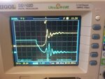
This oscilloscope image shows it better than I can explain it.

The blue trace is the low-side MOSFET gate voltage, shown turning off from 12V to 0V. The yellow trace is the high-side MOSFET switching on momentarily later, going from 0V up to Vdd +12V (around 55V in this case). Notice the low-side oscillates when the high-side is turned on.
This is the schematic of the half-bridge

The driver IC is the LM5104M (sorry for it not being on the schematic).
Series resistors on the gate of the MOSFET's were present (10R), but they made the problem worse (they lengthened the period of the oscillations), so I removed them.
Also, increasing the dead-time or the boot-strap capacitance (I doubled it from 420nF to 840nF) did not have any effect.
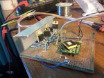
The circuit is made on strip-board, and I have tried to make the gate wires as short as possible. The image below shows the board in-case its relevant. The SMD IC in the middle is the driver IC, the two TO-220 packages bolted to the heatsink are the MOSFET's (the other two are schottky diodes), and that plug-in module is a 35-75V to 12V buck converter for powering the IC from the 60V rail voltage.

After many h-bridge revisions (4 in total), I have almost got it working. The one remaining problem that I can't seem to solve is that the low-side MOSFET experiences oscillations when the high-side MOSFET is swtched on. I think this is causing shoot-through and causing the power rail voltage to sag momentarily. The bulk capacitors on the power rail where heating up, supporting this theory. The MOSFET's also get un-naturally warm once you start drawing more than an amp through them (by my calculations, they should still be dead cold at this point). These oscillations get worse as the current increases, so the shoot-through is more severe at larger currents.
I am driving the brushed 36V, 800W at the outputs.
This oscilloscope image shows it better than I can explain it.

The blue trace is the low-side MOSFET gate voltage, shown turning off from 12V to 0V. The yellow trace is the high-side MOSFET switching on momentarily later, going from 0V up to Vdd +12V (around 55V in this case). Notice the low-side oscillates when the high-side is turned on.
This is the schematic of the half-bridge

The driver IC is the LM5104M (sorry for it not being on the schematic).
Series resistors on the gate of the MOSFET's were present (10R), but they made the problem worse (they lengthened the period of the oscillations), so I removed them.
Also, increasing the dead-time or the boot-strap capacitance (I doubled it from 420nF to 840nF) did not have any effect.
The circuit is made on strip-board, and I have tried to make the gate wires as short as possible. The image below shows the board in-case its relevant. The SMD IC in the middle is the driver IC, the two TO-220 packages bolted to the heatsink are the MOSFET's (the other two are schottky diodes), and that plug-in module is a 35-75V to 12V buck converter for powering the IC from the 60V rail voltage.
