Continue to Site

Welcome to EDAboard.com

Welcome to our site! EDAboard.com is an international Electronics Discussion Forum focused on EDA software, circuits, schematics, books, theory, papers, asic, pld, 8051, DSP, Network, RF, Analog Design, PCB, Service Manuals... and a whole lot more! To participate you need to register. Registration is free. Click here to register now.

Lecroy 9310M Oscilliscope help

Status
Not open for further replies.

Bruce101

Junior Member level 1
Joined
Feb 2, 2012
Messages
16
Helped
0
Reputation
0
Reaction score
0
Trophy points
1,281
Location
Central Ma. U.S.A.
Activity points
1,396
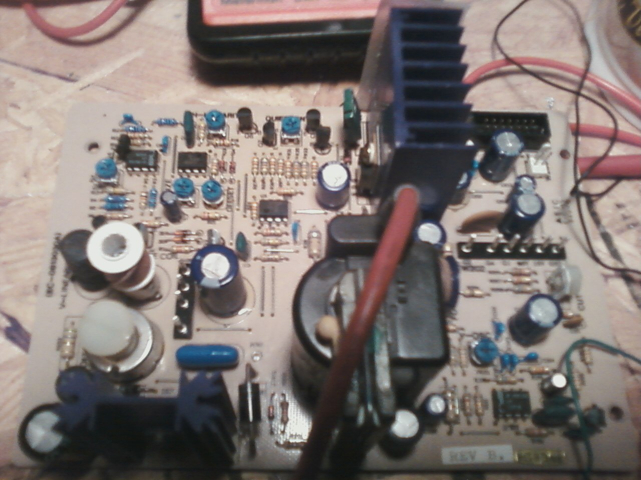
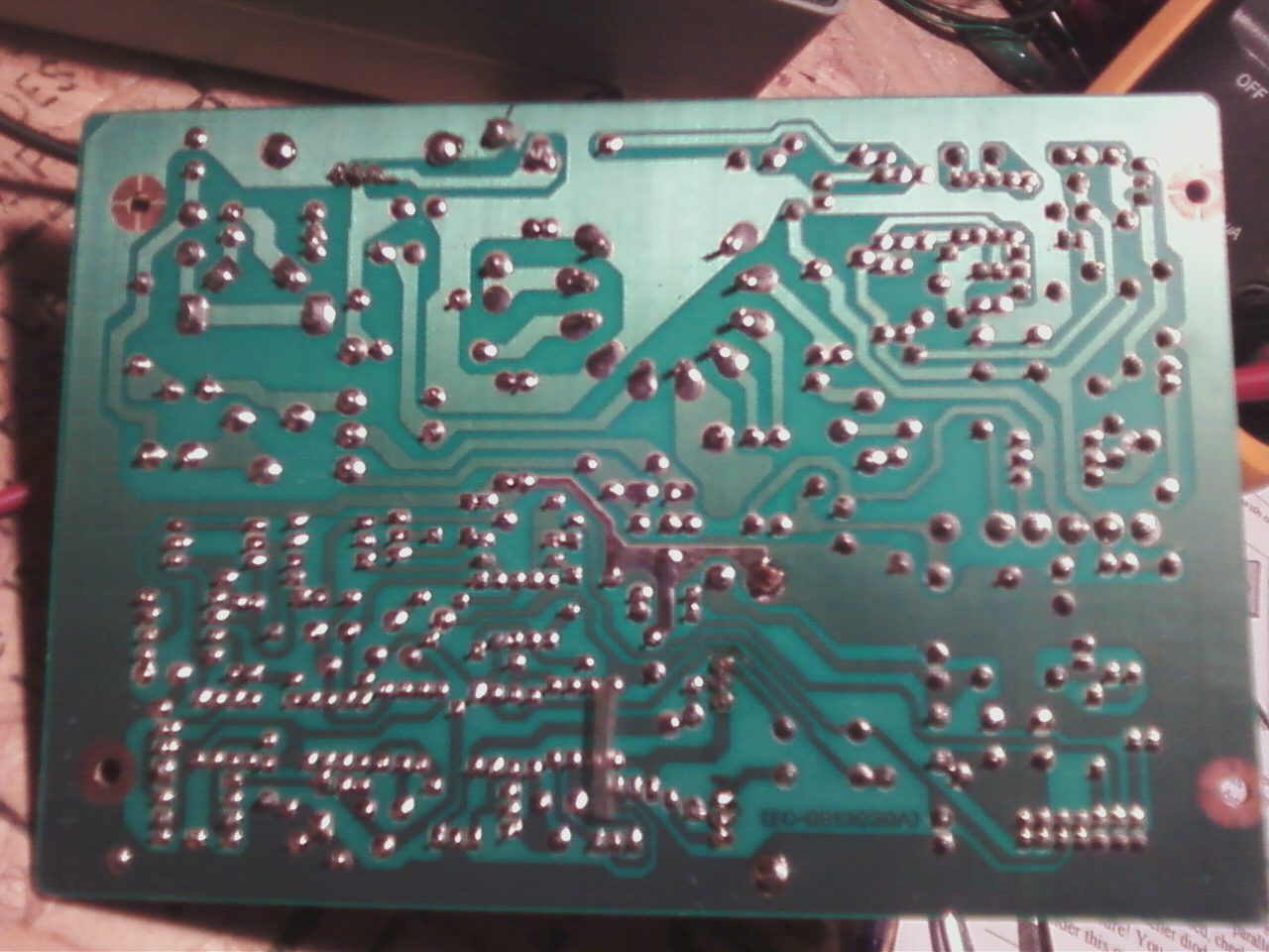
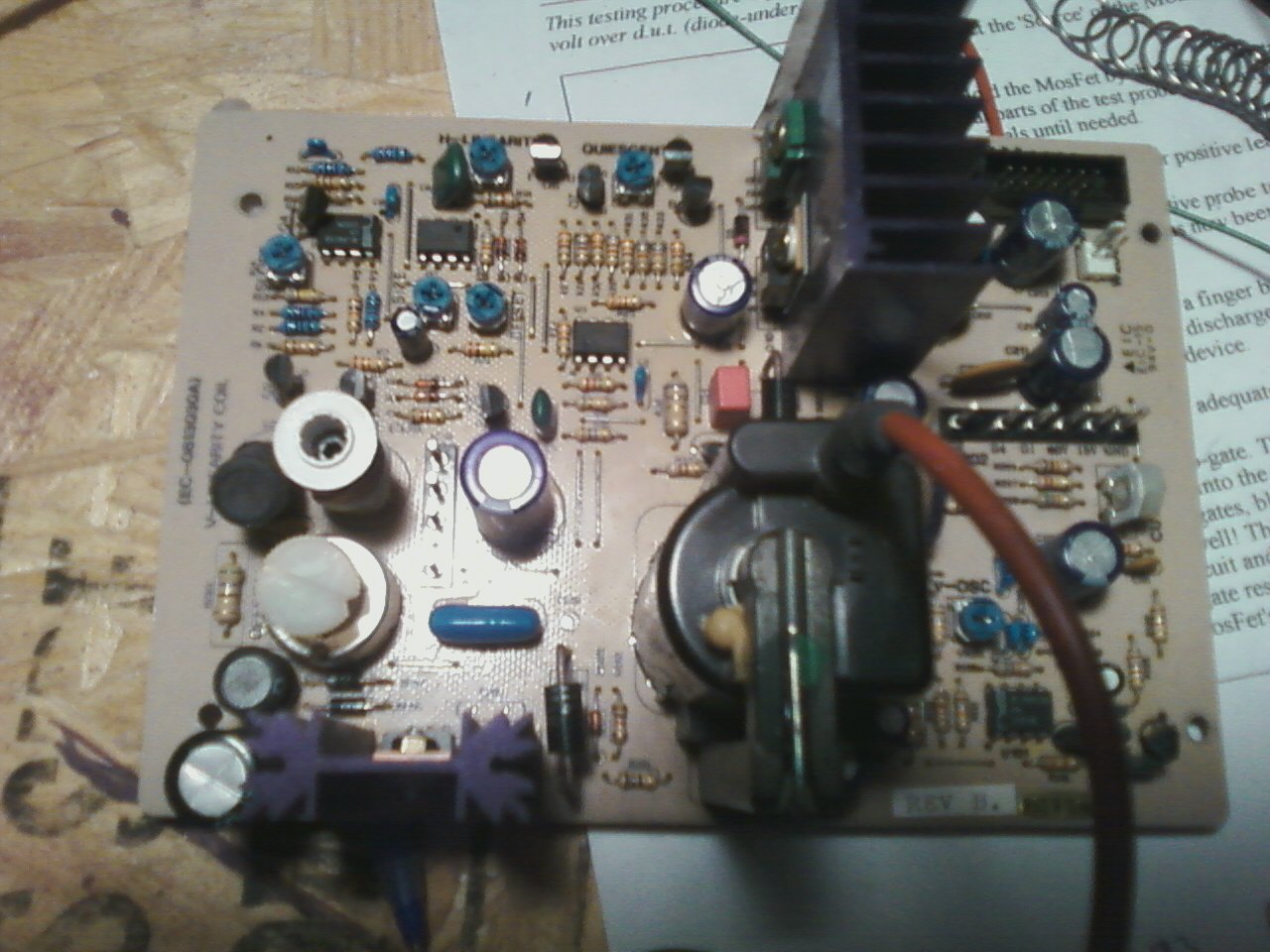
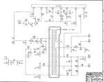
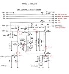
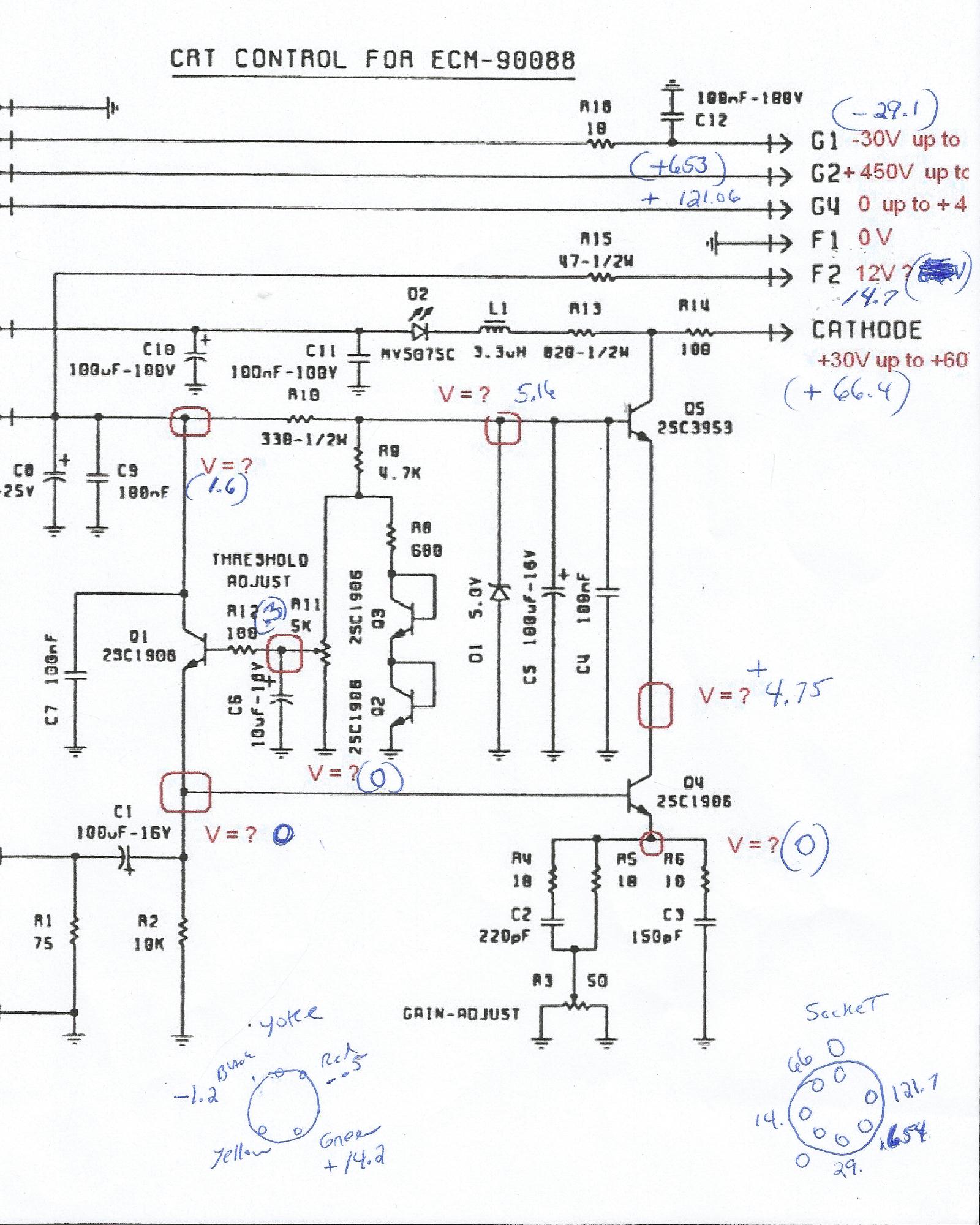
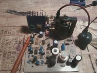
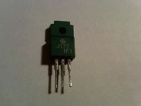
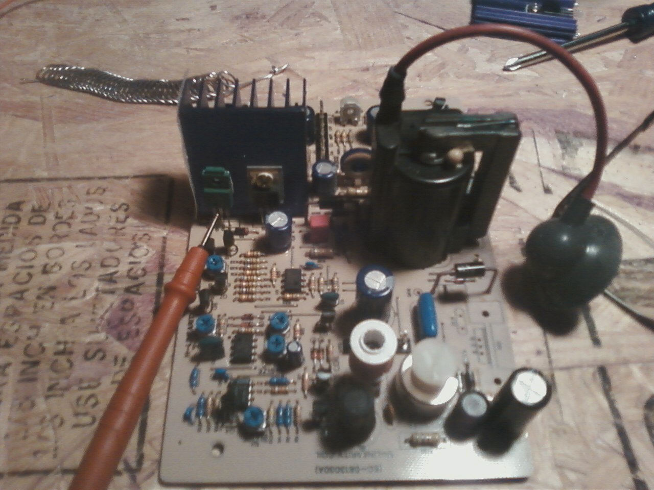
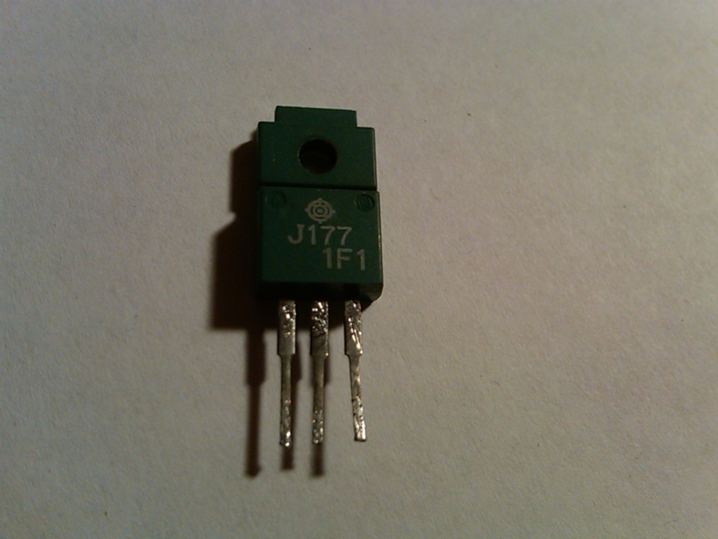
Looking for part number for Q5 on the power board that houses the high voltage for the CRT. Part is Marked J177. see picture
My scope has no video on screen no voltage to coil on crt neck. can some one please ID this part that red lead is pointing to.


thank you
 

2SJ117

Silicon P-Channel MOS FET,
Drain to source voltage VDSS –400 V
Gate to source voltage VGSS ±20 V
Drain current ID –2 A
Drain peak current ID(pulse) –4 A
Body to drain diode reverse drain current IDR –2 A
Channel dissipation Pch*1 40 W
 

Attachments

  • 2SJ117.pdf
    69.2 KB · Views: 49
I tested the P-MOSFET. Source to Drain is shorted all the time will not drain. gate to drain +/- and -/+ open. source to gate open. drain to gate open. Using a Fluke 87 . I would say it a dud ?
 

It seems so. Do a final test connecting some 10V-25V negative power supply output via 100-220 ohms resistor to the drain terminal, with the gate shorted to the source terminal, and all together to the positive wire. Measure the drain – source voltage, normally same value as the power supply…
 
Funny thing, I check it. using 11.8 volts. came out reading 11.00 volts drain to source. I pulled the two other Mosfets and did the same test. IRF630 and IRF 740. they were fine, changed the power supply
 
Last edited:

Until now that’s a good result for testing the 2SJ117 at 12V, but we can't give a final verdict without final testing the P-Mosfet at 200-300V.
The IRF630 and IRF 740 are N-Channel Power MOSFET type transistors, so need to change polarity of the power supply. ;-)
By the way, can you post here some photos of the PCB power board? Maybe problems related to other components that fails in high voltage board.


---------- Post added at 11:30 ---------- Previous post was at 11:28 ----------


Thank you.

Bruce /Ka1tzy
 

Need also some PCB solder side sharp photos... :-D
 

Placed all the Mosfet back on the board. Checked the Video board. transistor Q305 it's a C3953. ordered one from mouser. The mouser nte2508 I think is a dud. builted a simple tester and seems the NTE2508 came as a dud. My gut feeling has always been the C3953. Thats why I ordered the replacement last week. what do you think. I ordered a new NTE2508

NTE2508
CE pair: LED off both ways. My EC on / Ce Off
BC pair: LED bright with red lead on B, LED off the other way. My BC on / CB off
BE pair: LED bright with red lead on B, LED off the other way. My BE on / EB Dim.

C3953 removed from video board.

CE pair: LED off both ways. My CE off /EC on
BC pair: LED bright with red lead on B, LED off the other way. My BC on / CB Off
BE pair: LED bright with red lead on B, LED off the other way. My BE On /EB On


79_1328556856.gif


Here are pictures of back of power board and back of Video board. There is Voltage at the front plug on the power board. But G5 has 0.600 volts.voltage at Video board is ok also. did find a shorted dione in back of the net2508 on the video board next to the Cap. No part number ?.


Tx's
Bruce/Ka1tzy
 
Last edited:

I think we are focusing on a wrong direction… :cool:
Before we start replacing defective components, please describe in detail the actual problems encountered for this equipment.
Later, based on that info we may start measuring in circuit voltages (and in the ideal conditions if possible, start observing some wave-forms) in order to help us for a correct diagnose about what may be causing the trouble and which components should be replaced.

See partial schematics of the deflection PCB attached.
 

Attachments

  • Deflection.JPG
    Deflection.JPG
    144.3 KB · Views: 85
Will Do. going to work today and working late. the problem is no video and no waveforms onscreen. board that is supplying voltage to power board has a mini LED. that LED is lit. that's the long board on right looking from the front. CRT neck tube is lit. CRT has some burn in marks on screen. LED on board that is attached to CRT socket has a LED this LED was very dim then went out . When I power on and off I can hear the high voltage in the CRT.
 
Last edited:

Please receive the service manual for 9314A/C AM/CM/AL/CL:
 

Attachments

  • Lecroy_9314_sm.pdf
    11 MB · Views: 80
More details about power supply on page 182 ( 7-30 SM).
Read also on page 171 (7-19; 7-21 SM) some troubleshooting steps to be considered.
 

Attachments

  • CRT.JPG
    CRT.JPG
    94.6 KB · Views: 71
  • amplifier.JPG
    amplifier.JPG
    117.5 KB · Views: 64
  • power s.JPG
    power s.JPG
    70.4 KB · Views: 61
Steve Thanks for the reply. on the int crt I only have 60 volts on the cathode. D2 not lit. I have a feeling crt is gone. On the yoke what should be the voltage on the coil. on the green I have 30 volts. I check the voltage on all the boards Video and def board. and the Mosfet. all ok. IC's all seem to have the right voltage -15/+15. any clue on how to check the CRT. Voltage on socket to crt all the right voltage also. So feeling is CRT or Yoke. Thank's. Bruce /TZY
 

I have simulated the two theoretical situations for adjusting pots ''min'' and ''max'', see details in the attached pictures. Need to do real measurements on the CRT board in the indicated points, by adjusting potentiometers from minimum to maximum value. :cool:
 

Attachments

  • CRT_1a.JPG
    CRT_1a.JPG
    99.1 KB · Views: 52
  • CRT simul 2a.GIF
    CRT simul 2a.GIF
    33.9 KB · Views: 63
Well. checked all the voltages. seem all in range. see attachment. CRT tube elements is lit. D2 LED not lit at cathode. If the CRT is gone what is my option.
 

Can you check what happens to the 15V power supply line? :???:
 

Attachments

  • 15V line.JPG
    15V line.JPG
    49.7 KB · Views: 63

Status
Not open for further replies.

Similar threads

Part and Inventory Search

Welcome to EDABoard.com

Sponsor

Back
Top