Continue to Site

Welcome to EDAboard.com

Welcome to our site! EDAboard.com is an international Electronics Discussion Forum focused on EDA software, circuits, schematics, books, theory, papers, asic, pld, 8051, DSP, Network, RF, Analog Design, PCB, Service Manuals... and a whole lot more! To participate you need to register. Registration is free. Click here to register now.

look for help about igbt short protection

Status
Not open for further replies.

466576266

Member level 1
Joined
Mar 22, 2010
Messages
36
Helped
0
Reputation
0
Reaction score
0
Trophy points
1,286
Location
ShangHai,China
Activity points
1,541
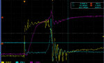
hello. i recently in the process of the igbt short protection. but i meet with a little problem.
my igbt driver CANNT protect the igbt when the igbt is in the short circuit condition.
i use the VLA500-01 driver which is from isahaya, and the igbt module is CM1400DU-24NF.
the attachment is one of a picture from the ocilloscope. the yellow qurve stands for the VGE voltage,
the purple qurve stands for the current of the emitter of the igbt, and the blue stands for the VCE voltage of the igbt.

can someone give me some help, its ergent.thans in advance.
 

Attachments

  • Snap1.jpg
    Snap1.jpg
    119.3 KB · Views: 99

The curve looks plausible so far. It looks like the IGBT is destroyed by the huge overvoltage during emergency switch-off. The only way to reduce the overvoltage are soft switch-off and dynamic clamp. But they don't necessarily work for any load circuit.

I wonder, if this is a realistic short circuit scenario or an artificial test setup?

from the datasheet of the cm1400du, the maximum VCE is 1200V, it seems that the the VCE voltage is about 1250V(5*250) which exceeds the rated value a little.
and i think it is no problem.

and this is an artificial test, please see the attachment, it is the experiment setup.
by the way, have u ever used VLA500-01 before?
 

Attachments

  • test setup.jpg
    test setup.jpg
    98.9 KB · Views: 91

The inductive overvoltage is nevertheless very high related to bus voltage. The question is, if you are measuring the voltage correctly. You should also the consider, that the inner chip voltage will be higher than the external one. This is particularly true with a low inductance short, as you have it in your setup.

As another point, Vce should be limited by the operation of the high side diode in a bridge circuit, which can't be seen in your measurement. This can happen even with reasonable bus voltage bypassing if the short inductance is too low, or due unsuitable bypassing.

If it's no an overvoltage induced breakdown, it's a case of too large absorbed energy. But according to the waveforms, the driver is acting on IGBT desaturation with acceptable delay. So I can't see a driver problem in this regard.

I'm not using VLA500-01. My experience is limited to Eupec driver modules and custom designed IGBT drivers. I notice, that the VLA500 has a slow switch-off feature, but doesn't support dynamic clamping. What's your Cs setting?

I would check for sufficient bus voltage bypassing with low inductance "snubber" capacitors and repeat the test with a more realistic short circuit impedance, involving a longer wires.
 

Status
Not open for further replies.

Part and Inventory Search

Welcome to EDABoard.com

Sponsor

Back
Top