Vermes
Advanced Member level 4

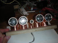
It is a clock that displays the time and date on NIXIE tubes LC-513. The tubes are mounted in copper elbows with a diameter of 28mm, which are mounted to two linked plywoods. The whole electronics and the chime of an old clock are placed between the plywoods. The chime strikes every hour the actual time. Elbows with tubes also serve as the clock buttons which are operated by the touch of a finger. The elbow with the dot is equipped with the sensor of the remote control. Atmega32 controls the work of the clock, because is has the appropriate number of pins to be able to control in BDC drivers 74141. One such chip is used for one of the tubes, so there is no multiplex display. Additionally, a timer of the processor is set for the PWM generator, which allows tubes brightness adjustment. Time is measured in a popular system PCF8583, which, together with battery, provides continuous timing. The arm of a hard disk 2,5” after appropriate adjustment was used as the “drive” to the chime. The coil on the arm is controlled by the dual bridge H-L293, in this case only one of the bridges is used. Controlling by touching the tubes with a finger is realized in a simple transistor amplifier circuit, with an appropriate filter at the output, which is directly connected to the input pin of the processor. This solution reacts to network frequency – 50Hz, which is transferred to the input of the amplifier after touching by a finger. In order to increase the sensitivity of this solution and allow operation through lacquered tube, the mass of the clock was connected to zero and to the phase voltage through two capacitors 470pF. The clock closed in the housing, unfortunately, is no longer “open”, because the inscription on the front is “pressed into” the plywood and then the whole was lacquered with a clear varnish. The program in the processor can be changed by preloaded bootloader based on RS232, which is released on the back of the clock on the DB9 connector. Power the clock is also through this connector by voltages 200V to Nixie tubes and 9V to power all the electronics.
Pictures below show the clock (it was not painted yet):
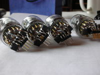
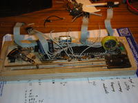
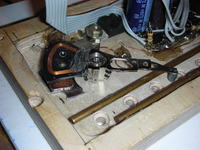
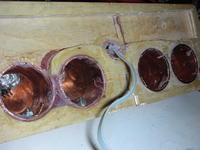
Link to original thread (useful attachment) – Niksik - Zegarek z lampkami NIXIE