Continue to Site

Welcome to EDAboard.com

Welcome to our site! EDAboard.com is an international Electronics Discussion Forum focused on EDA software, circuits, schematics, books, theory, papers, asic, pld, 8051, DSP, Network, RF, Analog Design, PCB, Service Manuals... and a whole lot more! To participate you need to register. Registration is free. Click here to register now.

which level sensor should be used for this project ?

Status
Not open for further replies.

dineshdeshmuk

Full Member level 5
Joined
Sep 12, 2011
Messages
285
Helped
18
Reputation
36
Reaction score
18
Trophy points
1,298
Activity points
3,131
which level sensor should be used for this project ?

the sensor would be hanged in the tank of a cooling tower so that the water level not exceed the required limit ....

Case 1 :
the pump should get start when the water level is low & off when the water level is maximum

Case 2 :
the pump should get off when the water level reaches to its maximum marked level and after that some man start the pump manually (and then after filling the tank to the required level the pump should stop again automatically)

3 phase motor (pump)

kindly , design the circuit for both these cases , i badly need these for my task

thanking You
 

A simple float switch should fulfill your requirements.

I have used a variety of float switches to control a tanks liquid level in numerous designs.

The size and dimensions of the tank as well as the operating temperature are some the the required specs for the selection of an appropriate float switch.


Other options include ultrasonic and capacitive sensors:


**broken link removed**

Each option comes with its particular benefits and drawbacks, select the appropriate sensor of your designs requirements.

BigDog
 

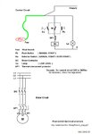
I drew a circuit for you.............
Water level control, used in machine cooling systems.
tested and reliable implementation

Case 1 :
the pump should get start when the water level is low & off when the water level is maximum
Selector Switch in AUTO position

Case 2 :
the pump should get off when the water level reaches to its maximum marked level and after that some man start the pump manually (and then after filling the tank to the required level the pump should stop again automatically)
Selector Switch in MANUAL position

Lamp indicates Low level

Float switch technical prochure
**broken link removed**

Cool_Tow_Pump_Control_01.jpg
 
Traditionally, float switches are used for this purpose. As the most simple solution, mechanical switches, that can directly control a 3-phase motor, are available since more than 50 years, and still manufactured these days. I assume, that similar devices are available in your country.

ftp://ftp.moeller.net/DOCUMENTATION/AWA_INSTRUCTIONS/IL05212002Z2011_06.pdf

Besides these classical, ruggedized level control solutions, all kinds of electronic level switches can be used.
 

I think you have made a mistake, kak111 as when MC pulls in it's contact above it is made and there is nothing to switch MC off.
For case 1, you need two level switched, one to switch the pump on at the "low" level, and another to switch it off at the tank "high level".
case 2 :
"the pump should get off when the water level reaches to its maximum marked level * and after that some man start the pump manually (and then after filling the tank to the required level~ the pump should stop again automatically)"
This does not make sense.
* = tank filled up OK same as case 1
~ = then what - tank over flows? or is ~ the maximum level and * some intermediate (chosen) level.
Frank
 
the fsw is a 24vdc or 240 vac ???

can anybody provide me the schematic of needed or any pcb needed for this ??
 

if i use 24 vdc fsw then how to convert ac into dc ? with power supply or battery ???
 

If only loads are one contactor and one lamp
I suggest industrial power module 240Vac // 24Vdc / 1...1.5A
( eg. Din rail Power supply )
 
what capacity overload should be used with the contactor (3 phase) ? What coil voltage should be used 440V or 230V ?
What size breaker should be used ? Would it be handy to use 3 phase magnetic starter after the breaker or not ?

thanks all
 

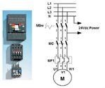
Motor thermal relay MF1 , look set value from motor name plate.
Contactor coil voltage = control circuit voltage.
If 24Vdc used in control then coil voltage = 24Vdc.
If 240Vac used in control then coil voltage = 240Vac.

Supply switch MSw , if MCCB type used look table for set value

Motor power .... MCCB setting .... Thermal relay setting
Look at table below (device types are from ABB product line)

3-Ph_Mot_Control_01.jpg
3_ph_Mot_ThermalProt&MCCB_ABB.jpg
 
Status
Not open for further replies.

Part and Inventory Search

Welcome to EDABoard.com

Sponsor

Back
Top