Continue to Site

Welcome to EDAboard.com

Welcome to our site! EDAboard.com is an international Electronics Discussion Forum focused on EDA software, circuits, schematics, books, theory, papers, asic, pld, 8051, DSP, Network, RF, Analog Design, PCB, Service Manuals... and a whole lot more! To participate you need to register. Registration is free. Click here to register now.

Testing and evaluation of AC Voltage stabilizers

Status
Not open for further replies.

nazeerhussain

Newbie level 5
Joined
Nov 24, 2011
Messages
9
Helped
0
Reputation
0
Reaction score
0
Trophy points
1,281
Activity points
1,356
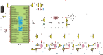
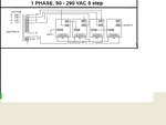
I want to build an AC voltage stabilizer relay type in the range of 2KVA to 5KVA capacity operating voltage between 160 to 260 volts AC, frequency 50HZ. The thing I am stuck on right now is that after completion of project how I test/calibrate the voltage stabilizer. Can any one send me any such procedures to be followed for testing/calibration and reliability of Voltage stabilizer? Does any particular test equipment will be required for that purpose.
Respected Readers may submit either a link or PDF files. Waiting hear at the earliest.
Thanks for the help
Regards,
nazeerhussain
 

You should know trafo will be very big for 5KW.

Example of voltage corrector :


You can perform simple test with autotransformator, decrease voltage and see does device working.
 

Attachments

  • image003.gif
    image003.gif
    34.4 KB · Views: 140
Last edited:
Any body can explan here autotransformer (multi tape) taping design .

Sahu its simplest transformer design. Autotransformer have only one coil.


Auto Transformers are actually built with the equivalent of only one winding. Two-winding transformers can be connected to reproduce the same effect. The single winding version has as a limit that it is most efficient when the difference between the input and output voltages are closest. As the difference becomes greater, efficiency suffers, and so does the advantage of this design.

While an Auto Transformer loses the advantage of the isolation existing between two separate windings, there are several advantages to an Auto Transformer.

A single circuit that is split into a primary and secondary produces the desired effect using less materials for both wire and core. This is economically desirable.

In Auto Transformers converted from two-winding transformers, they lose some advantage in savings of materials, but gain back economic advantage by virtue of the in-series nature of the configuration causing it to produce far higher output.

Lower losses contribute to increased efficiency.

Less material used results in lower weight. This can be a factor in where and how they are installed, and the difficulties encountered. It can also be a positive factor in portable applications.

Reactance is reduced in an Auto Transformer and thus results in better regulation characteristics.
 

Attachments

  • 300px-Tapped_autotransformer.svg.png
    300px-Tapped_autotransformer.svg.png
    9.6 KB · Views: 157
@tpetar Hi !
is there any free software to design the winding turns required for autotransformers
for a given input and output voltage?
I searched in Google but could not find any
thanks
 

@tpetar Hi !
is there any free software to design the winding turns required for autotransformers
for a given input and output voltage?
I searched in Google but could not find any
thanks


Of course all for my friends, there it is for current :
**broken link removed**


there it is for voltage :
**broken link removed**
 
Last edited:
@tpetar
thank you very much indeed for the links
regards
Tipu
 

Of course all for my friends, there it is for current :
there it is for voltage :
**broken link removed**
its very nice ,thanks
but it only for step down .
my need both are (step up + step down) . as Attached u post in #post no 5.
 

Attachments

  • stb.PNG
    stb.PNG
    28.9 KB · Views: 144
Status
Not open for further replies.

Similar threads

Part and Inventory Search

Welcome to EDABoard.com

Sponsor

Back
Top