alina khan
Junior Member level 1
how to use moc3020 and 4N25 in one circuit
any circuit diagram??????????
any circuit diagram??????????
Follow along with the video below to see how to install our site as a web app on your home screen.
Note: This feature may not be available in some browsers.
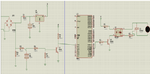
This example is a classic dimmer system for lighting
") and understood same thing u told but afta some time
and understood same thing u told but afta some time