holabr
Member level 2
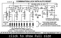
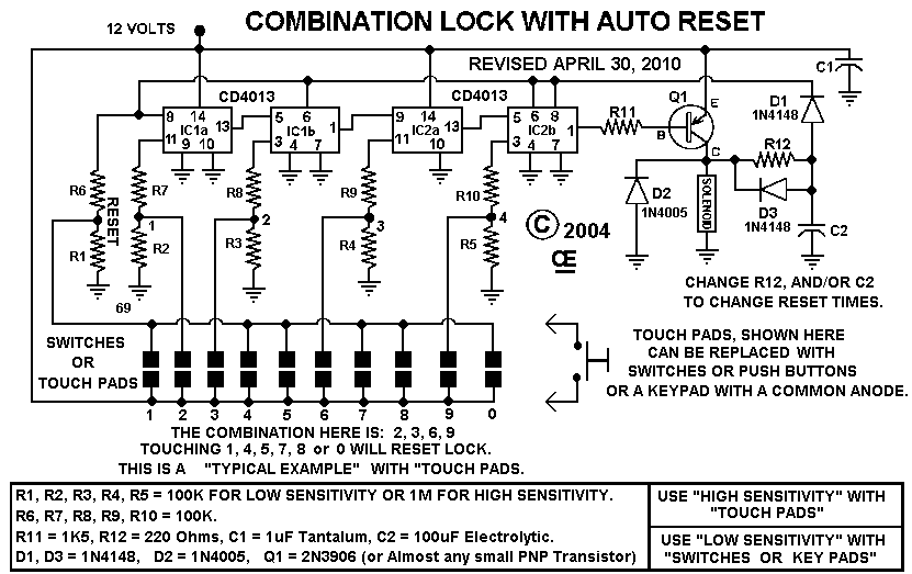
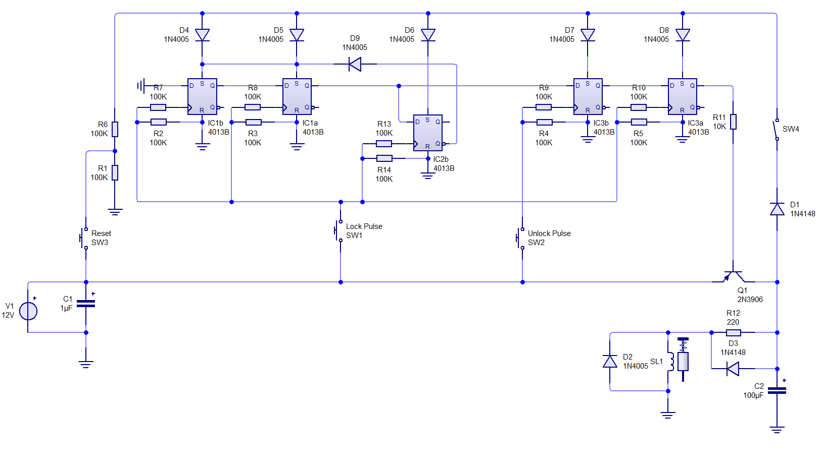
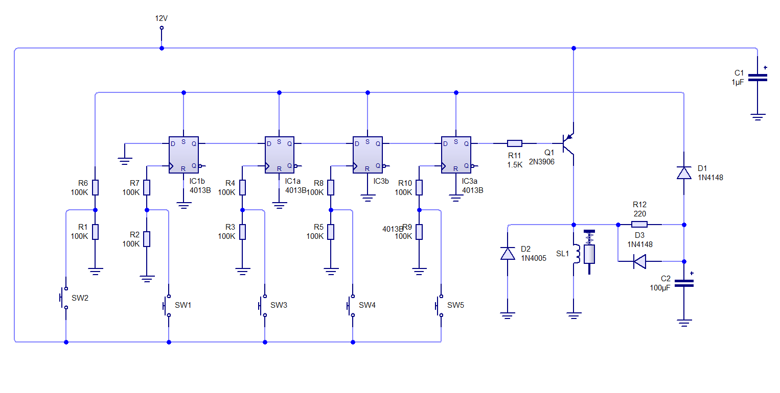
I have an aftermarket remote start module in my car that has its own remote. The unit also has a test lead that will start the car when it is grounded momentarily. Since my car has an OEM remote to lock and unlock the doors built into the key, I would like to build a simple circuit possibly using CD4013 flip-flops to use a combination of lock and unlock pulses (like lock-lock-unlock-lock)within a set period of time to close a relay to ground the test wire. I would pick up the pulses from the 12volt lines going to the door lock solenoid in the drivers door. Logically, when the first lock pulse comes in, it would trigger the first flip-flop and start a timer. If the following pulses arrive within the time period in the proper order, the relay would energize. If not, the circuit would reset and wait for the next lock pulse. I found the attached schematic as a starting point but it does not allow using the same input pulse more than once. Any ideas? Is there another IC that steps the output to a different pin with every pulse of an input? That way the first "lock" pulse would look like SW2, the next like SW3 and the third like SW9.