Vermes
Advanced Member level 4
It is an analogue, monophonic radio that can work near the computer on the desk.
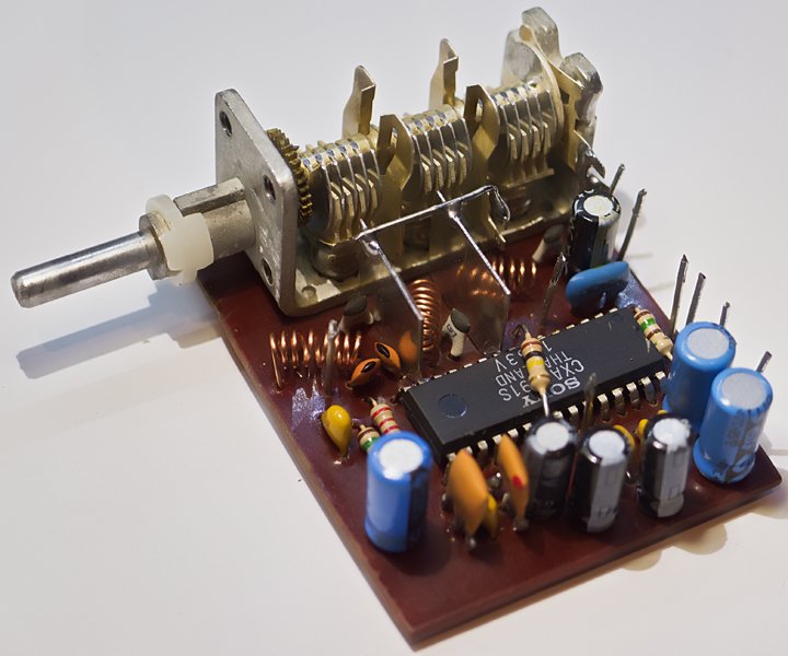
The device is based on a popular system Sony CXA1191, which ensures good parameters of receive and high sensitivity. The resistance to interference needs a decent mount and screening of individual high frequency blocks. Therefore, the individual sections: input, high frequency amplifier and heterodyne are separated from each other with tin surfaces. Similarly, the bottom of the plate is mostly covered with a screen, which can be made of steel can.
The photo shows how to protect the sections.
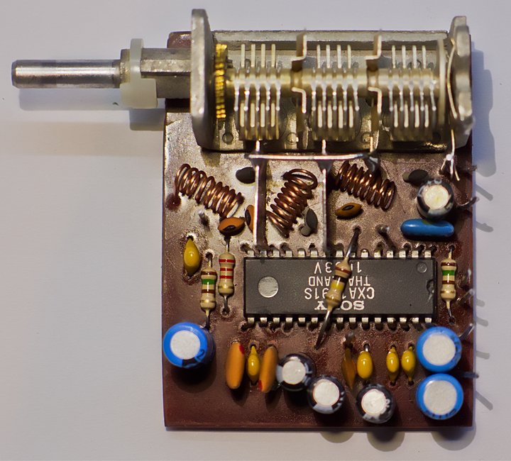
Systemic solution is simple, although there are four coils there. All of them were wound with a wire from UTP on 3mm drill and have 7 turns. The fourth coil connecting the system to an antenna (not visible in the photo) has 30 turns. The antenna is a 20cm section of guitar string, which has good elasticity and provides self-support. Of course you can use any other conductive material. Remember that the longer the antenna is, the less turns of the coil will be located next to it.
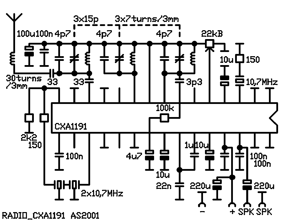
Three-sections tuning capacitor (unit) was used. Also a classic two-sections capacitor may be used instead, tuning the antenna circuit permanently on the medium of the band (part from the left side). For this purpose, capacitor 4,7pF should be changed to 10-12pF. Outputs, after attaching the unit, combine by wire of UTP rigidly with original outputs on the plate. Please note that the capacitor housing (stator, which is also the screen) and the screen are not connected with the mass, but with the reference voltage, which occurs at high surfaces of the plate and 9 leg of the system.
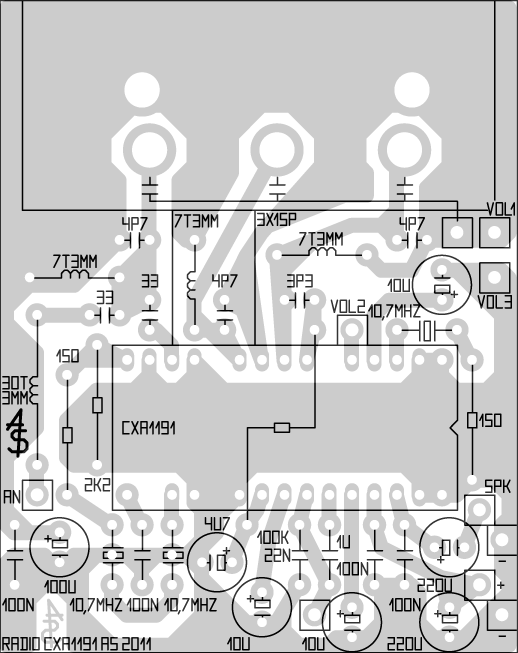
When all the elements are embed according to data from the schema, at least part of the station should be immediately received. The whole band should be “put” into the range of tuning by squeezing or stretching the heterodyne coil. This must be done after mounting the screens with a plastic or wooden stick. Then look for possible weak station in the middle of the range and stretch or squeeze the center coil to minimize noise. Then do the same with the first coil – the effect is smallest (and therefore replacing variable capacitor with a constant value will not affect significantly the receive). On the end, verify the coil connecting the antenna with the radio, but the impact will also be small.
Any speaker can be plugged to SPK outputs.
The system is powered by 3-7,5V stabilized voltage.
Link to original thread (attachment) – Proste radio FM oparte o CXA1191