genxium
Junior Member level 3
How can I distinguish "feedback loop" and "active gain loop" in a Hartley Oscillator
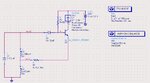
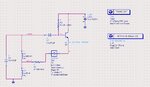
I'm currently learning to use harmonic balance simulation for an Oscillator, and started with a Hartley Oscillator, but I don't know how to put the OSCPORT into the original circuit >_<
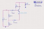
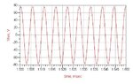
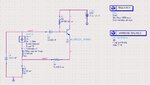
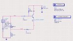
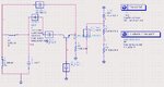
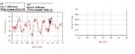
Here is my diagram that works in real devices test(@125 kHz, amplitude stable for half an hour), can anyone teach me where I can insert an OSCPORT to apply the Harmonic Balance simulation? It's said that I should put it to break the feed back loop, but I have no idea where it is...
I'm currently learning to use harmonic balance simulation for an Oscillator, and started with a Hartley Oscillator, but I don't know how to put the OSCPORT into the original circuit >_<
Here is my diagram that works in real devices test(@125 kHz, amplitude stable for half an hour), can anyone teach me where I can insert an OSCPORT to apply the Harmonic Balance simulation? It's said that I should put it to break the feed back loop, but I have no idea where it is...