Continue to Site

Welcome to EDAboard.com

Welcome to our site! EDAboard.com is an international Electronics Discussion Forum focused on EDA software, circuits, schematics, books, theory, papers, asic, pld, 8051, DSP, Network, RF, Analog Design, PCB, Service Manuals... and a whole lot more! To participate you need to register. Registration is free. Click here to register now.

Led driver ,dimmer pwm

Status
Not open for further replies.

zx10r05

Newbie level 4
Joined
Dec 11, 2011
Messages
5
Helped
0
Reputation
0
Reaction score
0
Trophy points
1,281
Activity points
1,317
Good morning to everybody. I am new of this forum, and I premise that, I very like the electronics but I'am not experienced. I would want to clarify some doubts that concern the led driver and the dimmers. I have purchased the following objects.:

**broken link removed**

**broken link removed**

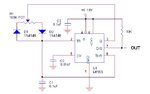
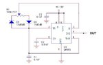
I would want to regulate the bright intensity of the led with a dimmer. On pin the marked dim in out side , that type of regulator should buy? Do it take a pwm generator or enough something simpler? could you help me please? I thank you in advance and excuses me for mine terrible English.

Alberto
 

It may or may not PWM....look LED's brightness is directly proportional to current flowing through them .....so either you reduce the voltage accross the LED will be give you less bright output...that can be managed by putting simple variable resistance in series with LEDS also.....Now comming back to PWM....what PWM dose is it alters the average voltage accross the LED based on the duty cycle ...this is more elegent way to get the LED brightness control.....the LED driver that you are shared....I think works on PWM....

Good Luck
 

I read well the datasheet. It says that an external pwm controlis requied . My problem is really this. A controller already exists to buy or it needs to build one ? If it needs to build it, where I find a simple scheme? I attach the documentation that I have found.

**broken link removed**

**broken link removed**

**broken link removed**
 

First, in order to use the 50W power LED you need also a proper heat sink, like this one:


A simple PWM controller can be made using a 555 circuit, some examples here:
**broken link removed**


For the power LED you need a 36V power supply, for the 555 a lower voltage 12V - 15V , so you may use two separate power voltage supplies or a supplementary power voltage regulator (LM317) to be used to generate the 15V from the 36V power supply.
 

Tanks, i have the heatsink and the power supply. Now I buy the components to build the circuit with the ne555. Do you know if they exist in commerce circuits as this already built?
 

You may buy different electronics kits for sale, to include the NE555/NE556 timers, see
**broken link removed**
LM555 Timer ICs Kit | eBay
also I have found for example a PWM kit which is sold locally in Romania:
**broken link removed**

but in my opinion those are too expensive to buy (including shipping and handling charges), and the PWM circuit it’s not so complicated to build, you need only one resistor, two diodes, capacitors, a small plated-thru hole PCB (prototyping board), some wires and one NE555 IC ( + IC socket) to start building the PWM circuit.
 

Attachments

  • PWM 1.JPG
    PWM 1.JPG
    19.7 KB · Views: 104
Thanks. I think that you are right and I will build the circuit. A small question... the pwm V out is not specified inyour the regulator. it depend on the imput Voltage or is it a constant value?
 

LED driver DIM input = digital input, the applied logical signal input must be either ‘on’ or ‘off’.
A ‘’low logic ‘’ (below 0.5V) at DIM input will disable the internal MOSFET and shut off the current flow to the LED and because there’s an internal pull-up circuit to ensures that the circuit is ON when pin DIM is unconnected, no need for an external pull-up resistor to obtain the ‘’high logic’’.

The DISCHARGE pin (number 7 ) of the 555 is a open collector output, so in this case you can connect directly the 555 to the LED driver circuit DIM input regardless the power supplied to 555 circuit…
 

Attachments

  • PWM 1 rev2.JPG
    PWM 1 rev2.JPG
    18.2 KB · Views: 67
ok, now I understood a little bit . You have been very kind. Among a few days I believe that I will build the circuit. Later I tell you as it works. Thanks very much.
Alby
 

Status
Not open for further replies.

Similar threads

Part and Inventory Search

Welcome to EDABoard.com

Sponsor

Back
Top